msp430 hello world

A couple of years ago the TI Launchpad made quite a splash when TI released the boards for just $5 each. The Launchpad uses the msp430 low power microcontroller from TI, these microcontrollers don't have the same pretty face as the avr microcontrollers in the AVR world.

This means the code is a little harder to read and write. It is a lot closer to assembly language than the high level Arduino C/C++. While it looks worse I find it more fun to write and it will leave you with a much better understanding of how the controller is working.

So lets load up a simple blinking light program(no more of that sketch nonesense), fire up the debugger and stop the code as it is executing. Grab the following code and make file and compile up the main.elf target. If you are using a different microcontroller then you should change the g2553 to the microcontroller you are using.

Blink Program

#include <msp430g2553.h>

int i = 0;
int j = 0;
int
main(void)
{
    WDTCTL = WDTPW + WDTHOLD;   //Stop the watch dog timer
    P1DIR |= 0x41;              //Set the direction bit of P1(0x01) as an output

    P1OUT = 0x40;               //Set P1.6 high, P1.0 low

    for(;;) {
        P1OUT ^= 0x41;          //Toggle both P1.1 and P1.6

        for(i = 0; i < 20000;i++){  //Loop for a while to block
            nop();
        }   
    }   
    return 0;
}

Makefile

CC=msp430-gcc
CFLAGS=-Os -Wall -g -mmcu=msp430g2231

OBJS=main.o

all: $(OBJS)
    $(CC) $(CFLAGS) -o main.elf $(OBJS)

%.o: %.c 
    $(CC) $(CFLAGS) -c $<

clean:
    rm -fr main.elf $(OBJS)

We use the mspdebug program to flash the program to the msp430 like so.

$ mspdebug -q rf2500
Trying to open interface 1 on 006
rf2500: warning: can't detach kernel driver: No data available
fet: FET returned error code 4 (Could not find device or device not supported)
fet: command C_IDENT1 failed
Device: MSP430G2xx3
fet: FET returned NAK
warning: device does not support power profiling
(mspdebug) prog main.elf
Erasing...
Programming...
Done, 152 bytes total
(mspdebug) run
Running. Press Ctrl+C to interrupt...
^C
    ( PC: 0c068)  ( R4: 0dff7)  ( R8: 0ffbb)  (R12: 0fdf7)  
    ( SP: 00400)  ( R5: 05a08)  ( R9: 0dcff)  (R13: 0fd67)  
    ( SR: 00004)  ( R6: 0b775)  (R10: 0dddf)  (R14: 0dfff)  
    ( R3: 00000)  ( R7: 0ff1f)  (R11: 0dfff)  (R15: 00000)  
main+0x2a:
    0c068: f9 3b                     JL      0xc05c
    0c06a: f2 3f                     JMP     0xc050
    0c06c: 32 d0 f0 00               BIS     #0x00f0, SR
    0c070: fd 3f                     JMP     0xc06c
    0c072: 30 40 76 c0               BR      #0xc076
    0c076: 00 13                     RETI    
(mspdebug) exit

There you have it, your first hello world on the msp430.

libnfc i2c usage

I have been working on applications using the SPI user space api. One of the devices I have been playing with is a PN523 NFC reader. The reader is supported by libnfc and can communicate using serial, SPI, i2c or usb depending on device support.

I wanted to get the nfc reader working over i2c, to form a baseline to compare it against SPI. I couldn't get the nfc-list to show any NFC devices connected to the Pi. I then tried to use the i2c -s command to scan the i2c bus, but instead of device detection the command threw an error.

It turns out that the iic driver for the Pi only supports one ioctl, I2CRDWR. That neuters most of the FreeBSD i2c tools as they use other ioctl's and error out on failure.

Learning that I looked at the Makefile for libnfc, this time realising that the i2c and the SPI device options are both commented out. I missed this the first time I looked at the FreeBSD port, there is still the option to use a serial device once I dig out a usb serial adapter.

It is looking a lot harder than I thought to get devices working with user space SPI on FreeBSD. It doesn't help that Linux has been the only operating system with user space SPI support for quite a long time.

User SPI Adventures

Last year I started working on a project in the space that I thought would be pretty cool, a Mystery Box. I made a box out of foam board, mounted a servo as a catch. Inside I wired up an Arduino to control the servo. The Arduino connected to a Raspberry Pi over SPI, I used SPI because it was a nice simple protocol to implement on both the Arduino and the Raspbery Pi.

The Mystery Box was going to run a BBS which had control over the servo. My idea was to use the box as a simple CTF target, with the servo giving instant and substantial feedback for success.

Around this time I had been asked to port NewCWV to FreeBSD, we wanted to have more than one implementation of the proposed standard available. Doing some development in the FreeBSD kernel made me want to look at using the operating system in other places.

Up to this point I had been using Linux on the Pi in the Mystery box, but I thought it would be fun to try FreeBSD. FreeBSD on the Pi was in a reasonable state, I didn't have trouble getting the Pi to boot. When it came to controlling the Arduino over SPI I hit a snag.

There wasn't (and still isn't) user space SPI support in FreeBSD. This means that I can control devices to connected to SPI from a kernel driver, but I can't do so from user space. Kernel code is harder to write, not portable and means I can't reuse Linux code. User space code is easier to write and if the interface is similar to existing ones I can reuse a lot of other code.

I was enjoying writing the NewCWV port and I thought to myself: "I should make the world a better place and write a user space SPI layer". And that is exactly what I set out to do over the next few months.


This week, well over 9 months later I finally have a working SPI layer. I can issue, read(2), write(2) and ioctl(2) commands and see the bus burst into life with data flowing across.

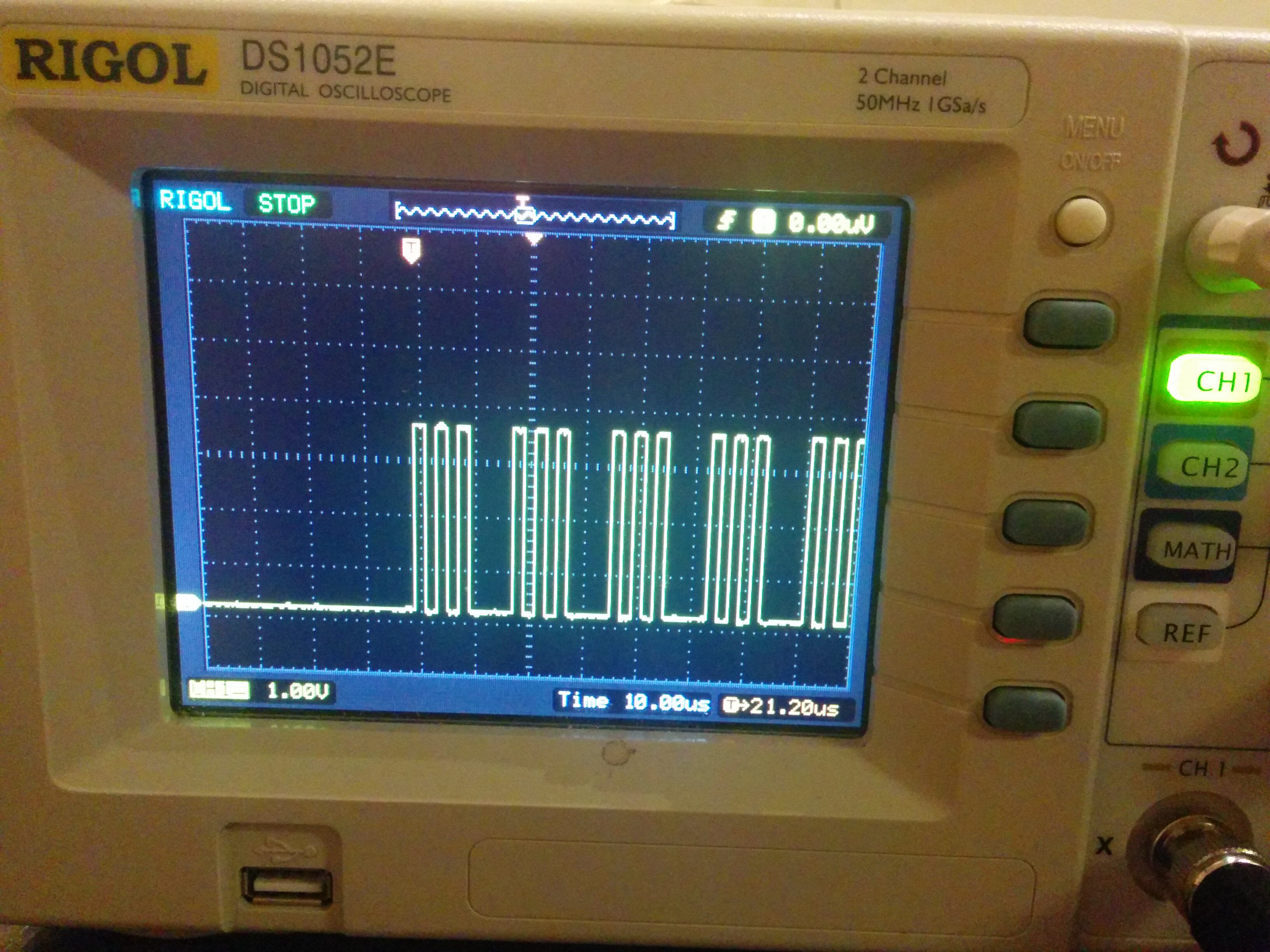
On the other end of the bus I have a Trinket Pro (Adafruit arduino clone). The Trinket acts as a SPI slave, when there is activity on the bus it spits on the values from the master over UART and writes the SPI values back onto the bus with 10 added.

The Arduino seems to struggle at the default bus speed of 500KHz, but runs fine when I lower the speed with a sysctl down to 50KHz.


Speaking to the Arduino is okay, but it doesn't make a very exciting demo. I had a couple of devices that can be controlled over SPI, a SSD1306 OLED Screen and a PN532 NFC Reader .

The NFC Reader is supported by libnfc , a quick look shows that libnfc is available in the FreeBSD ports tree. I looked at the libnfc code while writing the user space layer and it seemed pretty straight forward. libnfc opens the SPI device and calls the SPI IOC MESSAGE ioctl to send spi ioc transfer structs to the driver.

The interface I have written is a little different, using an object to describe the transfer similar to the way iic(4) works. To add FreeBSD support I need to create the struct and swap the ioctl(2) call, this should be straight forward.

Using the OLED is a little different. Adafruit have provided a python library to speak to the screen using either i2c or SPI. The python library imports a module to speak to SPI and seems to mostly use read(2) to control the screen. This is going to be harder to port across and get working.

There is also an Adafruit Arduino library for the SSD1306 and Arduino compatible boards. This is C++ that has been written to run on an Arduino rather than on a unix machine. This code could probably be slimmed down, with the calls to fastspiwrite swapped out to calls to the kernel interface.


My implementation is still a little rough around the edges, the code needs to be tidied up, moved into the kernel directly and tested on the latest head. I think that getting user space code working with it will show up any bugs, it will certainly make for more meaningful test cases.

My next step is to get the NFC reader working with libnfc and the raspberry pi, then I can start work on the screen. Once I have some SPI examples working I might even get back to setting up the Mystery Box for a CTF in the space.

31c3

31c3 Finished 21 days, probably enough for me to get past the conference high, but also enough time for me to catch up on almost all of the talks. All of the talks from 31c3 and most of the other congresses have been put online at media.ccc.de .

I took notes during Congress, but I had a hard time turning them into a post. If anyone wants to see my notes I am sure they could appear. Instead here are some thoughts.

Congress is Europe's largest temporary art installation. The CCH is a simply massive building, after 5 days of wandering around the I am still not sure I saw everything. It wasn't until day 4 of Congress that I realised the floor numbers were not floor numbers, but actually the Saal you were closest to. The ones and twos I could see around me were not helpful directions.

The building was augmented by the CCC to make it a home for hackers. The lights were dimmed, there were blinkenlights in every corner and just to make things even better there seemed to be a pop up interactive installation at random intervals. A pneumatic tube system was run around the ground floor of the building.

Of course there were talks 12 hours of the day, but the talks were streamed later. There were too many things that could only be found in the 4 days of Congress to sit in a full lecture theatre.

Instead we held court at our table in the international hackerspace village. Hung around with the crazy cooks in the Food Hacking Base , argued politics in Noisy Square and wandered the cavern is a daze.

At night(due to the lighting it was hard to tell when that was) we would be at our table hacking on something super cool, or hiding in the amazing nightclub.

It is probably impossible to describe congress, there is just too much happening. It is probably unfair to try and give someone else a picture, the only real way to know what it is like is to experience it.

Join us next year.

Strange Mast

Walking home from the hackerspace last night I came across this interesting mast behind a car parked on the pavement. I had to grab a picture of this strange thing on Union Street.

The guy operating the mast spotted me taking the picture and came down for a chat. This mast was acting as a 4G base station, there was a second vehicle driving around the city, listening for this mast to map 4G propagation. It turns out that Aberdeen city council are planning to roll out 4G across the entire city, with free access. The council want to use this for fleet management and I think it is probably part of their initiative to improve bandwidth in the city.

According to the operator of this mast the 4G won't just cover the city center, they have been mapping industrial estates in Altens and out towards the edges of the Bridge of Don