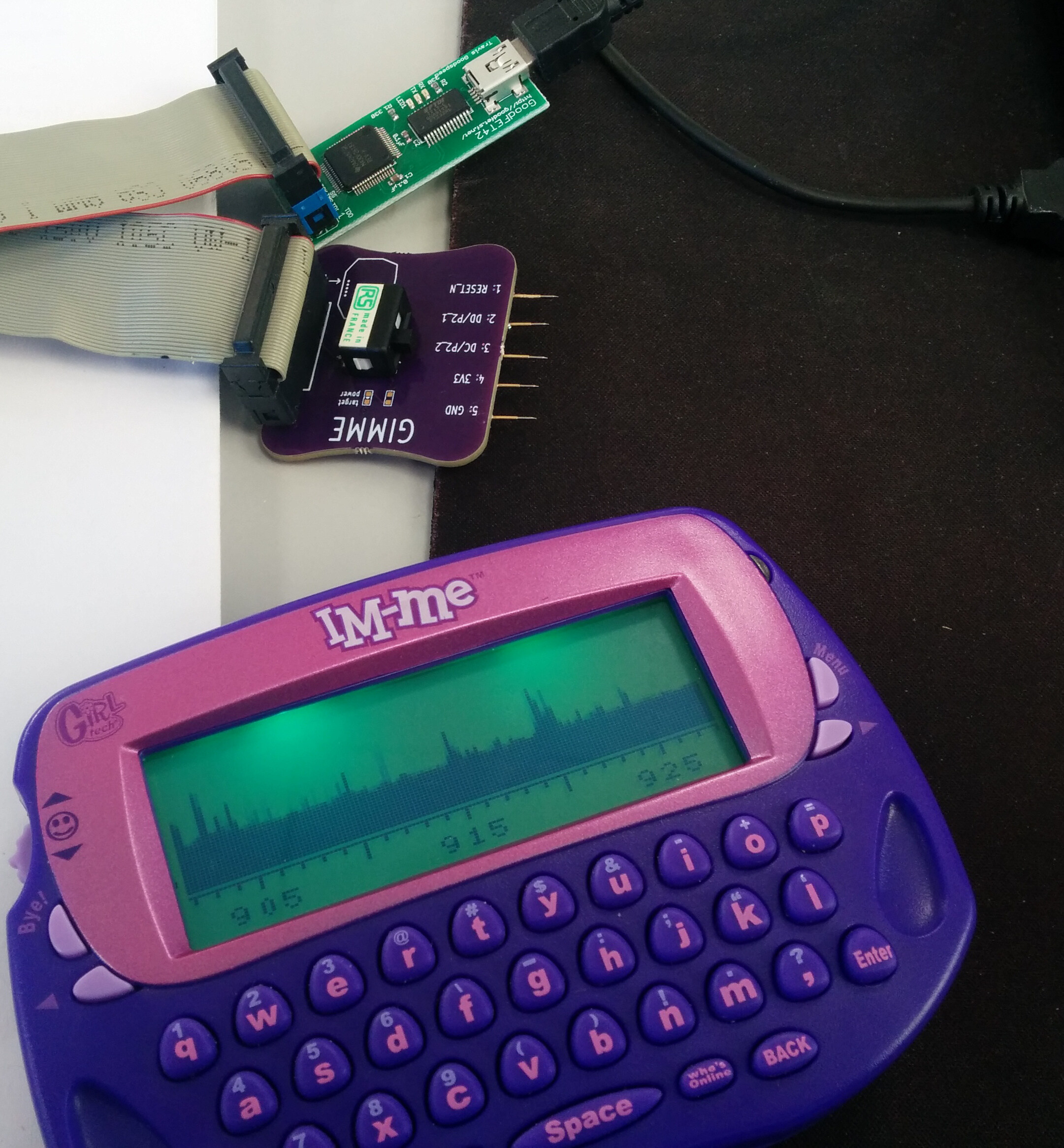
Just before I left work yesterday I built one of the gimme boards I got earlier
this week and connected it up to a
goodfet
. I had to do a little source editing
to let the goodfet run and connect to the correct serial port. If you need to
change the serial port from the default it is a quick grep through the source
tree to find literal string "/dev/ttyU0" to change.

I followed the instructions on the
git repo for the specan code
. The first
time I ran the flasher the IM-ME booted into the stock firmware again. I
erased the flash, tried again and it all worked. I am not sure how long the
flashing took, but if you will be holding gimmme expect it to be a few minutes.
To flash the IM-ME I did:
$ goodfet.cc erase
$ goodfet.cc flash specan.hex
This turned out to be a lot easier than I expected, everything seems to be well
documented. If you can get an IM-ME and want to flash it with a goodfet and a
gimme, send me an email and I will send you one of my spare(partially
assembled) boards.
My
Yardstick One
appeared yesterday, time to set up RFCat.
RFCat has not yet been packaged on FreeBSD so I had to install it manually. I
pulled the
RFCat source from bitbucket
which includes both the firmware
and the client tools. To play with the stock firmware on the YSO I just had to
install the client tools.
The client tools depends on
libusb-1.0
, which ships in FreeBSD and on
pyusb
. Pyusb is offered by the py27-usb port.
$ sudo pkg install py27-usb
Then I built the rfcat client tools:
$ cd code
$ hg clone ssh://hg@bitbucket.org/atlas0fd00m/rfcat
$ cd rfcat
$ sudo python setup.py install
I had to set up devfs rules to access the usb devices, with my account in the
usb group I have the following:
# /etc/devfs.rules
[localrules=10]
add path 'usb/*' mode 0660 group usb

#/etc/rc.conf
devfs_system_ruleset="localrules"
devd_enable="YES"
With that all set up I can now try the rfcat tools
$ rfcat -r
'RfCat, the greatest thing since Frequency Hopping!'

Research Mode: enjoy the raw power of rflib

currently your environment has an object called "d" for dongle.  this is how
you interact with the rfcat dongle:
    >>> d.ping()
    >>> d.setFreq(433000000)
    >>> d.setMdmModulation(MOD_ASK_OOK)
    >>> d.makePktFLEN(250)
    >>> d.RFxmit("HALLO")
    >>> d.RFrecv()
    >>> print d.reprRadioConfig()
The r flag tells the client to throw me into the research prompt and I get left
in something that looks sufficiently like ipython. To test that everything was
working I decided to transmit some bytes in a loop in the ism 433 band.
In [1]: d.setFreq(433920000)

In [2]: d.setMdmModulation(MOD_ASK_OOK)

In [3]: d.makePktFLEN(4)

In [4]: d.setMdmDRate(4800)

In [5]: for i in range(0,15):d.RFxmit('\xDE\xAD\xBE\xEF');

In [6]: for i in range(0,15):d.RFxmit('\xDE\xAD\xBE\xEF');

In [7]: quit()

I used an rtlsdr dongle and
sdrtouch
on my phone to get a quick demod of
the spectrum and to see a waterfall. I tried this a few times, but I wasn't
seeing the expected signal. Right off to the far right edge of the screen I was
seeing a jump in strength, tuning around a bit while transmitting I eventually
caught my burst packet. It seems that my rtl dongle is about 400KHz off the
actual observed frequency.
With the launch of the
yardstick one
I remembered the
im-me
I bought
earlier this year. Not wanting to risk destroying one of the last available
im-me's in the world I decided to get pcbs made of Michael Ossmann's
gimme
.
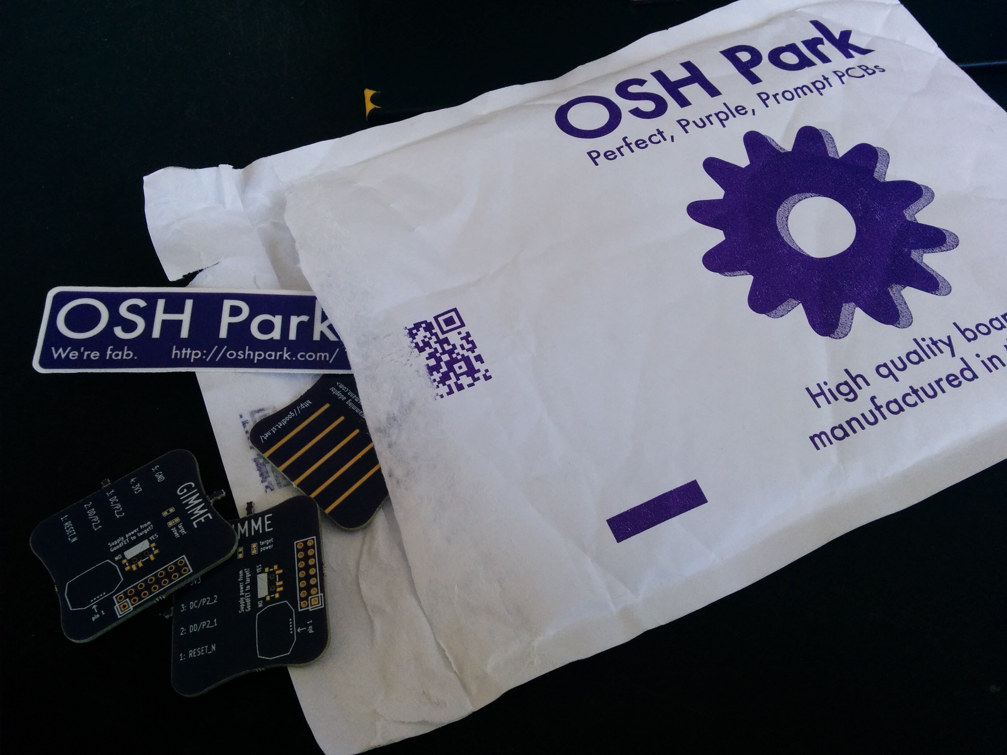
I found
a link to the OSH Park
board page an ordered a small batch(3
boards) for less than £10. They came in about 3 weeks and seem to be reasonable
quality, I will try them when my goodfet appears this week.

My main laptop is a Lenovo x220 Tablet with an an awesome swivel screen. The
screen on the laptop is a touch screen and wacom tablet which uses a pen that
hides in the side of the laptop.
I had quite a bit of trouble getting this all setup. Wacom touch and pen
devices are supported by
webcamd
in FreeBSD. I set up webcamd as
documented elsewhere on the internet and while I could see webcamd grabbing the
input devices the touch screen or pen didn't work at all under X.
Eventually I figured out the problem was xorg not detecting the hid device
nodes. To solve this I had to manually create an xorg.conf and the following
sections.
Section "ServerLayout"
    Identifier     "X.org Configured"
    Screen      0  "Screen0" 0 0
    Screen      1  "Screen1" RightOf "Screen0"
    InputDevice    "Mouse0" "CorePointer"
    InputDevice    "Keyboard0" "CoreKeyboard"
    InputDevice    "stylus" "SendCoreEvents"
    InputDevice    "touch" "SendCoreEvents"
EndSection

...

Section "InputDevice"
    Driver        "wacom"
    Identifier    "stylus"
    Option        "Device"       "/dev/input/event0"
    Option        "Type"         "stylus"
    Option        "USB"          "on"                 # USB ONLY
    Option        "Mode"         "Absolute"           # other option: "Absolute"
    Option        "Vendor"       "WACOM"
    Option        "tilt"         "off"  # add this if your tablet supports tilt
    Option        "Threshold"    "5"   # the official linuxwacom howto advises this line
EndSection

Section "InputDevice"
    Driver        "wacom"
    Identifier    "touch"
    Option        "Device"       "/dev/input/event1"
    Option        "Type"         "touch"
    Option        "USB"          "on"                  # USB ONLY
    Option        "Mode"         "Absolute"            # other option: "Absolute"
    Option        "Vendor"       "WACOM"
    Option        "tilt"         "off"  # add this if your tablet supports tilt
    Option        "Threshold"    "5"   # the official linuxwacom howto advises this line
EndSection
With the now xorg.conf dropped into /etc I could now restart the server and
boom, touch screen and tablet working quite well.
When I sniveled the screen I wanted to to be able to rotate my display and
input devices to the correct orientation. I wrote a little shell script that
can either advance the screen rotation by 90 degrees or set it back to the
default orientation.
#!/bin/sh

output=LVDS1
rotation="normal";

stylus="stylus"
touch="touch"

if [ "normal" == "$1" ]; then
    rotation="left";
else
    rotation=`xrandr --query --verbose | grep $output | awk '{print $5}'`
fi

case $rotation in
    normal)
        xrandr --output $output --rotation right
        xsetwacom --set "$stylus" Rotate cw
        xsetwacom --set "$touch"  Rotate cw
    ;;
    right)
        xrandr --output $output --rotation inverted
        xsetwacom --set "$stylus" Rotate half
        xsetwacom --set "$touch"  Rotate half
    ;;
    inverted)
        xrandr --output $output --rotation left
        xsetwacom --set "$stylus" Rotate ccw
        xsetwacom --set "$touch"  Rotate ccw
    ;;
    left)
        xrandr --output $output --rotation normal
        xsetwacom --set "$stylus" Rotate none
        xsetwacom --set "$touch"  Rotate none
    ;;
esac
I bound the script in my .i3/config to the two screen rotation buttons on the
fron of the bezzel. I found the keycodes by using xev.
bindcode 198 exec rotate normal
bindcode 204 exec rotate
Overall the touch screen and tablet work quite well. When webcamd starts it
doesn't always detect both the touch screen and tablet and sometimes in places
them at different event points. If I could figure out a way to make these
predictable or if a later xorg detects the input devices correctly then this
setup would be perfect.
There are a number of services out there that allow you to take a screenshot
and upload it to a website. All of these tools that I have seen(I didn't look,
at all) used have involved a proprietary service and uploading your images to
someone else's hosting.
That isn't good enough for me, I needed an open tool I could use anywhere
(FreeBSD support) with the ability to drop the resulting png into a directory
on a webserver I control.
Here is my tool to solve this problem, screenshot. Screenshot can capture
either the entire window or offer a picker to grab a certain area. I used
import from ImageMagick to handle the capturing and some glue to upload the
image. There is another option to open the image with feh if required.
$ screenshot open
$ screenshot upload
$ screenshot pick upload
The script also dumps file names and url into a log file, this makes it easy to
track down the last taken screen shots. I have some awk magic to pull out the
last url and throw it onto my clipboard.
#!/bin/sh

shotdir=$HOME/screenshots
site="mysite.me"
uploaddir="webdir/screenshots/"

if [ ! -d $shotdir ]; then
    mkdir $shotdir
fi

one=`word`
two=`word`

word=$one-$two.png
file=$shotdir/$word
name=`basename $file`
url=$site/screenshots/$name

pick=false
open=false
upload=false

for var in "$@"
do
    if [ "$var" = "pick" ]; then
        pick=true
        continue;
    fi

    if [ "$var" = "upload" ]; then
        upload=true
        continue;
    fi

    if [ "$var" = "open" ]; then
        open=true
        continue;
    fi
    file=$var
done

echo "File:" $file

echo $file "http://"$url >> $shotdir/screenshot.log

if $pick; then
    import $file;
else
    import -window root $file;
fi

if $upload; then
    scp $file $site:$uploaddir/$name
fi

if $open; then
    feh $file
fi
I use another shell script to generate a random word. This script uses my local
system dictionary, /dev/random and some glue to get a random word. The glue
uses three bytes read from /dev/random and uses od to format those bytes into
something useful. I then use sed to seek to the line in the dictionary to get
the word.
#!/bin/sh

words="/usr/share/dict/words"

num=`od -An -N3 -i /dev/random`

line=$(($num % `wc -l < $words`))

word=`sed -n "$line"p $words`

echo -n $word


