December Adventure 2025
I learned about December Adventure in the middle of December last year, which is probably quite typical. I don't think most people get the words out in sync with the hacking and so there is a delay. Obviously that didn't exclude me, it wasn't the spirit of the event after all, but I didn't have the capacity.
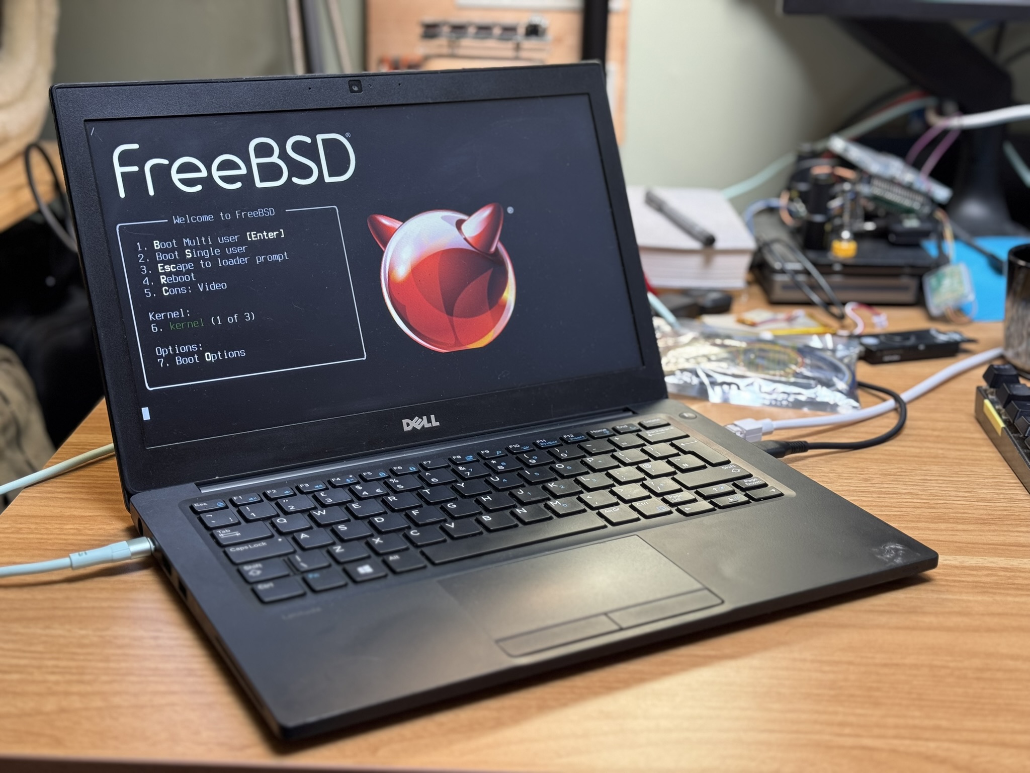
I thought I would make an attempt at December Adventure this year. I've been trying hard for a while to focus on about 1 thing at a time. I thought for DA this year I would try and make progress on this summers project: Port FreeBSD to the Allwinner H616.
This blogpost will update as I do stuff through December, so don't expect a real feed of updates. I want to keep the entry effort down to a minimum so most will be more running chain of thoughts rather than fully explained post. If you have questions send me an email and I'll add more detail until it makes sense. I am going to buck tradition and keep it in chronological order too.
Background
I was super intrigued by the Sipeed Nano Cluster when it was annouced and redacted video .
The Nano Cluster is a carrier board for up to 7 modules, with an integrated switch and network port. It is about the size of a small beer and fits in your hand. Sipeed designed 3 different modules that fit the form factor, a CM4/5 adapter, some AI SOC and a Allwinner H618 module based on the Orange Pi Zero3.
The H618 was the cheapest module on offer and Allwinner have a pretty good reputation of reasonable levels of hardware openness.
I ordered a cluster with two H618 modules to begin with, but the Sipeed project timeline wasn't very concrete. I wasn't really sure if these would ship in days or months and as it was June and I wanted a summer project I also went to Aliexpress and bought two different Android tv devices which advertised themselves as using the H616. Delivery times for me for Aliexpress stuff is somewhere between 1 day and 1 month so I thought I'd have a target to get started with.
You may have noticed me jumping between using H618 and H616, well that is because I couldn't keep the numbers straight in my head at all. In the end it turned out that the H616, H616 and H700 are all very similar and need the same hardware support. The H700 is actually in the Anbernic gaming device I got last year.
Anyway, with hardware bought and on its way to my home in Scotland I had to leave the country for the next three months on very short notice.
Summer 2025
Separated from hardware I was able to do some of the inital work on a port. I acquired the Nano Cluster files from Sipeed, but didn't look at them. I went digging into the first thing you need for an embedded port and acquired a device tree (source) file for the h616.
From there I was able to make a table mapping out which device tree nodes will be support by which existing drvier in FreeBSD. A lot of the time support is a matter for adding a compat string to a table and maybe some supporting data from the datasheet.
I got to the point where I had a table like this:
dts file: sun50i-h616.dtsi

mmio-sram
snps,dwmac-mdio
sun50i-h616-ccu                 per soc
sun50i-h616-crypto
sun50i-h616-dma                 a10_dma, a31_dmac (h3 config)
sun50i-h616-ehci
sun50i-h616-emac0               if_awg                  test
sun50i-h616-emmc                aw_mmc                  test
sun50i-h616-gpadc
sun50i-h616-i2c
sun50i-h616-iommu
sun50i-h616-ir                  aw_cir                  test
sun50i-h616-lradc
sun50i-h616-mmc                 aw_mmc                  test
sun50i-h616-musb
sun50i-h616-nmi                 aw_nmi                  not sure what this needs isn't in datasheet
sun50i-h616-ohci
sun50i-h616-pinctrl             aw_gpio
sun50i-h616-r-ccu
sun50i-h616-r-pinctrl
sun50i-h616-rsb                 aw_rsb                  needs config values
sun50i-h616-rtc                 aw_rtc                  need to check h3 table is correct
sun50i-h616-sid                 aw_sid                  needs config table (check linux)
sun50i-a64-sid
sun50i-h616-spdif               h3_padconf (and others)
sun50i-h616-spi
sun50i-h616-system-control      aw_syscon
sun50i-h616-ths                 aw_thermal              needs config table
sun50i-h616-usb-phy             aw_usbphy               needs config table
sun50i-h616-wdt                 aw_wdog                 needs config values
arm,cortex-a53
arm,gic-400
cache
snps,dw-apb-uart
arm,armv8-timer
arm,cortex-a53-pmu
arm,psci-0.2
fixed-clock
simple-bus
and the supporting patches for the changes I had made. This was a good to do list.
Then rather than getting to a point where I had builds, but no device I swapped summer project from "write some code" to read 15 books. This was cathartic and it finally settled a question from the last time I had a block of time off - yes reading a lot of books is good, but it doesn't leave you full, you have to do other things.
After Summer
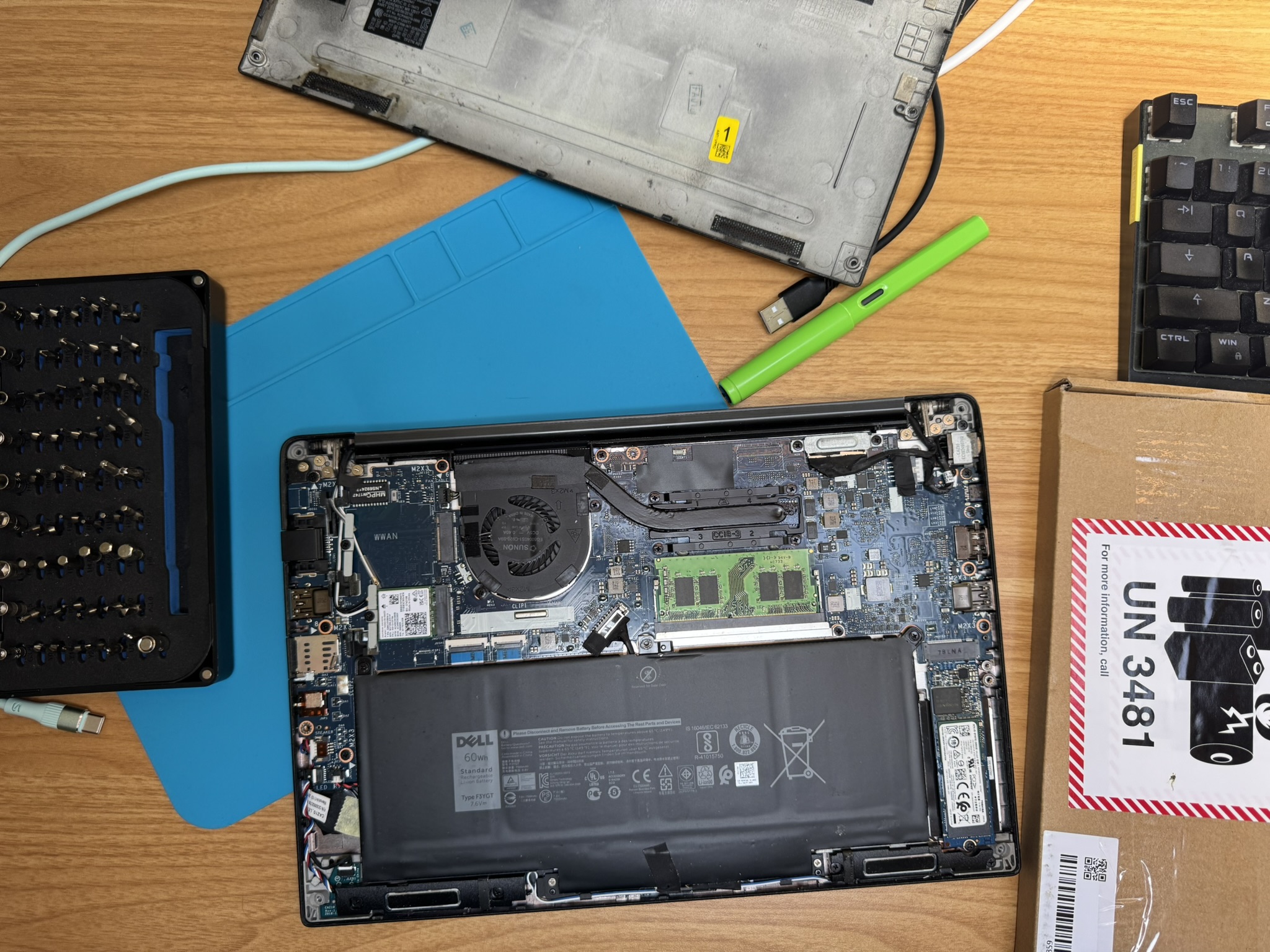
Once I finally made it home I unpacked the hardware, took the android boxes apart and photographed their insides (I'll add these pictures soon). The two devices were basically identical, they have a cool led panel on the front driven by gpio showing wifi status and disk access.
One is called a "H96 Max" or H96 for any files I dump from it, it has a blue PCB and the other is T95 Pro and it has a black PCB. Both boards have a pin header on the board by the SD card slot labeled with RX, TX, GND.
I connected PCB Bite probes to each and booted them up. They are both running android and drop you to a shell once they have booted. The H96 gave me a root shell, whereas the T95 gave me a user shell, so the H96 is going to get all the initial attention.
The H96 is very noisy once it has booted, I resolved [this by changing a logging sysctl] (https://superuser.com/questions/351387/how-to-stop-kernel-messages-from-flooding-my-console):
sysctl -w kernel.printk="3 4 1 3"
I wasn't able to break into uboot on either device, as far as I can tell from reading the uboot sources, you should be able to break into its prompt if it shows you "Hit any key to stop autoboot", but I couldn't manage.
With root on the system I instead dumped out uboot configuration from the emmc and used set to rewrite the autoboot delay field from 0 to 10. This didn't work, but it didn't work enough to stop the system booting, leaving me at a uboot prompt (so a win I guess?).
I saved a copy of the strings output of the uboot binary image I dumped, but in a fat fingered moment I overwrote the good original uboot config.
So that left me with a device I could boot and could access the uboot prompt on. That is more than enough to do a port from.
November Warm up
I realised December Adventure was coming and I killed the power supply in my other evening project really knocking my enthusiasm down a bit.
I set out to get a working development set up for the H96 before December started so I wouldn't be too bogged down.
I set up a usb serial adapter hanging off uart I soldered a header to. I added in an sdwire sd-mux board which allows you to share an sd card between a DUT and as TS. Finally to enable remote working on the device I added a pi pico running micropython and a relay to control power, giving me a remote off switch. This is really handy when you need to reboot a system from cold power on.
At some point I pulled a FDT off the board with something like:
# cat /sys/firmware/devicetree | nc host port
With that in place I then got the Sipeed sources building as a close enough initial target and copied out that uboot onto a PINE64-LTS FreeBSD 16 image.
FreeBSD provides aarch64 images, but Arm platforms are still a mess in the DTS
world and all require boot firmwares in different places. I checked through all
the build configs (
src/release/arm64/*config
) and verified that the
PINE64-LTS image has enough space before the first data partition to fit the
Allwinner uboot.
With all that background we can now move into the December Adventure log:
20251129
Image I built yesterday onto the freebsd pine64-lts image didn't boot. It is probably because I didn't set up the mdconfig image with sectors.
I tried copying to the sd card directly like so:
sudo dd if=build/u-boot-sunxi-with-spl.bin of=/dev/da3 bs=1024 seek=8 conv=sync
And managed to hit a useful error:
U-Boot SPL 2024.01-rc2-00076-g94b814f631e (Nov 28 2025 - 16:42:46 +0000)
DRAM:This DRAM setup is currently not supported.

resetting ...
I thought that maybe the h616 was like a NXP platform and that firmware specifics set the DRAM size and I spent a bit of time looking at ways the size might be configured. There isn't anything that responsible in the working dts, the memory section is commented out and the extracted dts doesn't indicate a range.
The extracted DTS doesn't build, which is its own issue for later.
I eventually grepped in the u-boot sources.
This hits a pretty unique bit of u-boot for this platform, which I have no idea what is needed to resolve.
For each type of memory there is a possible selection of bus widths and ranks. I'm not sure what ranks here means, so it is time to go to the datasheet.
The datasheet section on SDRAM is 1 page of bullet points.
There is a set of registers (20k) for
DRAM_CTRL
If the datasheet is no help I think I need to enable debug prints from u-boot. afsaf debug is defined in log.h and is enabled if DEBUG is defined in a file.
20251130
There is basically nothing in the user manual about the usage of the DRAM controller. This ties up really well with a comment or commit message in u-boot where the author says most values just come from the boot0 logs.
So now to enable debug on uboot and start littering the sun50iw9 paths with prints to see what actually happens before this DRAM error.
I am going to set the device tree back to the longan pi 3 one for test builds.
sudo sd-mux-ctrl --ts -e da12
sudo sd-mux-ctrl --dut -e da12
The first u-boot path came from the longan build scripts, this dd pulls u-boot from the actual build dir.
sudo dd if=build/uboot/u-boot-sunxi-with-spl.bin of=/dev/da3 bs=1024 seek=8 conv=sync
The value to define to get debug_ printfs is _DEBUG
/* Show a message if DEBUG is defined in a file */
#define debug(fmt, args...)                     \
        debug_cond(_DEBUG, fmt, ##args)
That gets us:
U-Boot SPL 2024.01-rc2-00076-g94b814f631e-dirty (Nov 30 2025 - 09:44:30 +0000)
DRAM:testing 32-bit width, rank = 2
read calibration failed!
testing 32-bit width, rank = 1
read calibration failed!
testing 16-bit width, rank = 2
read calibration failed!
testing 16-bit width, rank = 1
read calibration failed!
This DRAM setup is currently not supported.

resetting ...
More debug prints indicate that u-boot things this is lpddr4, but the boot0 log has:
[94]DRAM_VCC set to 1500 mv
[97]DRAM CLK =648 MHZ
[99]DRAM Type =3 (3:DDR3,4:DDR4,7:LPDDR3,8:LPDDR4)
[107]Actual DRAM SIZE =4096 M
[110]DRAM SIZE =4096 MBytes, para1 = 310b, para2 = 10000000, dram_tpr13 = 6041
[123]DRAM simple test OK.
So maybe this error is due to detecting the wrong ddr type somewhere.
Our copied u-boot defconfig has:
CONFIG_MACH_SUN50I_H616=y
# CONFIG_RESERVE_ALLWINNER_BOOT0_HEADER is not set
CONFIG_ARM_BOOT_HOOK_RMR=y
CONFIG_SUNXI_DRAM_LPDDR4=y
There isn't an unset version for ddr3, inventing one in the config breaks the build so there is some digging to do. The ddr3 config that uboot ships has the memory speed at 1333MHz, boot0 indicates the memory speed is much lower, but maybe we can just hacking this to work?
For some reason the uboot build is failing, but without stoping the makefile, which is pretty annoying. The real result is a lack of an output binary in the u-boot directory.
building u-boot constantly:
gmake clean; gmake sun50iw9-h616-h96_defconfig
gmake -j 16
Progress to a hang:
U-Boot SPL 2024.01-rc2-00076-g94b814f631e-dirty (Nov 30 2025 - 10:32:46 +0000)
DRAM:testing 32-bit width, rank = 2
mctl_phy_init:885 DDR3
mctl_phy_init:1114 READ CALIBRATION
read calibration failed!
testing 32-bit width, rank = 1
mctl_phy_init:885 DDR3
mctl_phy_init:1114 READ CALIBRATION
mctl_phy_init:885 DDR3
mctl_phy_init:1114 READ CALIBRATION
mctl_phy_init:885 DDR3
mctl_phy_init:1114 READ CALIBRATION
mctl_phy_init:885 DDR3
mctl_phy_init:1114 READ CALIBRATION
MBUS port 0 cfg0 0100000d cfg1 00640080
MBUS port 1 cfg0 06000009 cfg1 01000578
MBUS port 2 cfg0 0200000d cfg1 00600100
MBUS port 3 cfg0 01000009 cfg1 00500064
MBUS port 4 cfg0 20000209 cfg1 1388157c
MBUS port 5 cfg0 00640209 cfg1 00200040
MBUS port 6 cfg0 00640209 cfg1 00200040
MBUS port 8 cfg0 01000009 cfg1 00400080
MBUS port 11 cfg0 01000009 cfg1 00640080
MBUS port 14 cfg0 04000009 cfg1 00400100
MBUS port 16 cfg0 2000060d cfg1 09600af0
MBUS port 21 cfg0 0800060d cfg1 02000300
MBUS port 25 cfg0 0064000d cfg1 00200040
MBUS port 26 cfg0 20000209 cfg1 1388157c
MBUS port 37 cfg0 01000009 cfg1 00400080
MBUS port 38 cfg0 00640209 cfg1 00200040
MBUS port 39 cfg0 20000209 cfg1 1388157c
MBUS port 40 cfg0 00640209 cfg1 00200040
 4096 MiB
The ddr3 config option carrying a speed is pretty annoying. It is only considered in two places, one sets the type and the other is blob:
 static const u8 phy_init[] = {
 #ifdef CONFIG_SUNXI_DRAM_H616_DDR3_1333
         0x07, 0x0b, 0x02, 0x16, 0x0d, 0x0e, 0x14, 0x19,
         0x0a, 0x15, 0x03, 0x13, 0x04, 0x0c, 0x10, 0x06,
         0x0f, 0x11, 0x1a, 0x01, 0x12, 0x17, 0x00, 0x08,
         0x09, 0x05, 0x18
 #elif defined(CONFIG_SUNXI_DRAM_H616_LPDDR3)
         0x18, 0x06, 0x00, 0x05, 0x04, 0x03, 0x09, 0x02,
         0x08, 0x01, 0x0a, 0x0b, 0x0c, 0x0d, 0x0e, 0x0f,
         0x10, 0x11, 0x12, 0x13, 0x14, 0x15, 0x16, 0x07,
         0x17, 0x19, 0x1a
 #elif defined(CONFIG_SUNXI_DRAM_H616_LPDDR4)
         0x02, 0x00, 0x17, 0x05, 0x04, 0x19, 0x06, 0x07,
         0x08, 0x09, 0x0a, 0x0b, 0x0c, 0x0d, 0x0e, 0x0f,
         0x10, 0x11, 0x12, 0x13, 0x14, 0x15, 0x16, 0x01,
         0x18, 0x03, 0x1a
 #endif
 };
With no documentation, I'm not really sure what to do to get a compatible u-boot built. I can getting hold of the stock u-boot the board shipped with, either by chasing down whatever might be on the aliexpress listing from 6 months ago (lol), or by dumping u-boot from android and having a look at a disassembly.
I checked mount in android to find somewhere writable, this was /data/media
dd if=/dev/block/mmcblk0 of=h96rawdisk1M.img bs=1M count=1
and then I configured a static address to a test machine and used nc to copy the uboot dump off the device.
Then I dropped the first 8k of the disk to get a uboot blob:
dd if=h96rawdisk1M.img of=h96uboot.img bs=1024 iseek=8 conv=sync
this might not actually be all of uboot, but whatever.
Honestly, this is pushing what I can do with hardware re. I'm just not able to eyeball instructions out of an aarch64 hexdump yet.
I should switch to booting FreeBSD from an sd card using the vendor uboot, but maybe I could poke at this using radare2.
I mean, I might just need a series of writes to
PHYS_CTRL 0x0480000
, surely
that shouldn't be too hard to pull from uboot?
I spent the evening reading the radar2 book and looking up RE projects on uboot. While I was doing this the sunxi wiki was down, but later in the day it came back up.
The boot wiki page informated me that DRAM parameters are set between the board vendor and Allwinner using special tools, but they are carried as a configuration file at the start of the SPL boot loader.
That explains the
DRAM.ext
file in the uboot blob I extracted and gives me a
final (I promise) thing to try before paying attention to the port again.
20251201
I wrote up all my existing notes and added 1800 words - which hasn't really matched the "make entries easy" goal.
Installed sunxi-tools.
From yesterdays last minute discovery that there was tooling to help on the wiki I read more of the wiki pages on early boot.
The boot0 page includes a header for the boot0/spl, this is helpful for looking at the dump I took, even if I don't really need it.
    Offset  Name    Size    Notes
    0x00    B_INS   4       Branch instruction to Code Starting Point
    0x04    Magic   8       Ascii string "eGON.BT0" (No Null-terminated )
    0x0c    Checksum        4       Simple 4-bytes Checksum (Before calculate checksum this must be 0x5F0A6C39 )
    0x10    Size    4       Size of Boot0, it's must be 8-KiB aligned in NAND and 512-Bytes aligned in MMC
    0x14    Code    -       Code of SPL. The size depends on the processor and if it 's loaded from SPI, NAND or MMC
The DRAM settings sunxi wiki page has a link for getting parameters from boot0 https://linux-sunxi.org/U-Boot#DRAM_Settings, this is using 'sunxi-fw' which isn't in sunxi-tools on freebsd.
A little Makefile hacking later:
    diff --git a/Makefile b/Makefile
    index 8c16c01..23fe451 100644
    --- a/Makefile
    +++ b/Makefile
    @@ -1,6 +1,6 @@
     SH=/bin/sh
    -CC=${CROSS_COMPILE}gcc
    -CFLAGS=-Wall -g -O
    +CC=${CROSS_COMPILE}cc
    +CFLAGS=-Wall -g -O -I/usr/include -I/usr/local/include
     PREFIX ?=/usr/local
     all: sunxi-fw
And I had a working tool. Pointing it at my extracted uboot bits from the h96 showed something:
    $ ./sunxi-fw/sunxi-fw info -a h96rawdisk1M.img
    @   0: mbr: DOS MBR
            protective MBR, GPT used
            GPT version 00010000
            usable disk size: 29783 MB
            number of partition entries: 17
    @  16: boot0: Allwinner boot0
    @ 512: boot0: Allwinner boot0
but it wasn't great compared to the uboot I built myself:
    $ ./sunxi-fw/sunxi-fw info -a ../LonganPi-3H-SDK/build/uboot/u-boot-sunxi-with-spl.bin
    @   0: spl: U-Boot SPLv2
            DT: sun50i-h618-longanpi-3h
    @  64: fit: U-Boot FIT image
            fit:uboot: "U-Boot (64-bit)"
            fit:atf: "ARM Trusted Firmware"
            fit:fdt-1: "sun50i-h618-longanpi-3h"
            configuration: sun50i-h618-longanpi-3h
The eGON header is there in the dump, so I am not really sure what is wrong. Lets park that for now. The sdmux is painfully slow to dd a full image to, so last night as a last thing I left the computer copying over a fresh PINE64-LTS image, which shouldn't be able to boot at all.
Lets try and boot a kernel from the vendor uboot using the vendor uboot.
20251202
If I am going to use the vendor uboot then I can start working on getting a kernel booting at all from uboot. I have done this a ton of times on different boards and so I tried to track down an example command.
The best I could do was this:
    fatload mmc 1:1 0x48000000 dtb/starfive/jh7110-visionfive-v2.dtb
    fatload mmc 1:1 0x44000000 efi/boot/bootriscv64.efi
    bootefi 0x44000000 0x48000000

    fdt_addr_r=0x51ff8000
    kernel_addr_r=0x50200000

    fatload mmc 0:1 0x51ff8000 dtb/bl808-pine64-ox64.dtb
    fatload mmc 0:1 0x50200000 efi/boot/bootriscv64.efi
    bootefi 0x50200000 0x51ff8000
from my (unpublished) artilce on running FreeBSD on the Pine Ox64 riscv SBC.
It is all pretty straight forwards until we hit the
bootefi
command. I doubt
the uboot on the h96 has this. There are other options to boot a loader or
kernel, I'd prefer to use a efi loader if I can.
I aimed to do more in the evening at the hackerspace, but a stop off at Aldi on the way and forgetting a usb-c cable for my ridiculous setup stopped that.
20251203
Lets take a dump of the available uboot commands on the h96:
    Hit any key to stop autoboot:  0
    => help
    ?       - alias for 'help'
    base    - print or set address offset
    bdinfo  - print Board Info structure
    boot    - boot default, i.e., run 'bootcmd'
    bootd   - boot default, i.e., run 'bootcmd'
    bootm   - boot application image from memory
    bootp   - boot image via network using BOOTP/TFTP protocol
    cmp     - memory compare
    colorbar- show colorbar
    coninfo - print console devices and information
    cp      - memory copy
    crc32   - checksum calculation
    echo    - echo args to console
    editenv - edit environment variable
    efex    - run to efex
    env     - environment handling commands
    erase   - erase FLASH memory
    fastboot- fastboot - enter USB Fastboot protocol
    fatinfo - print information about filesystem
    fatload - load binary file from a dos filesystem
    fatls   - list files in a directory (default /)
    fatsize - determine a file's size
    fatwrite- write file into a dos filesystem
    fdt     - flattened device tree utility commands
    flinfo  - print FLASH memory information
    go      - start application at address 'addr'
    gpt     - GUID Partition Table
    help    - print command description/usage
    i2c     - I2C sub-system
    itest   - return true/false on integer compare
    loadb   - load binary file over serial line (kermit mode)
    loads   - load S-Record file over serial line
    loadx   - load binary file over serial line (xmodem mode)
    loady   - load binary file over serial line (ymodem mode)
    logo    - show default logo
    loop    - infinite loop on address range
    md      - memory display
    memtester- start application at address 'addr'
    mm      - memory modify (auto-incrementing address)
    mmc     - MMC sub system
    mmcinfo - display MMC info
    mw      - memory write (fill)
    nfs     - boot image via network using NFS protocol
    nm      - memory modify (constant address)
    pbread  - read data from private data
    poweroff- Perform POWEROFF of the device
    printenv- print environment variables
    protect - enable or disable FLASH write protection
    pst     - read data from secure storageerase flag in secure storage
    reset   - Perform RESET of the CPU
    run     - run commands in an environment variable
    saveenv - save environment variables to persistent storage
    screen_char- show default screen chars
    setenv  - set environment variables
    setexpr - set environment variable as the result of eval expression
    sleep   - delay execution for some time
    source  - run script from memory
    sprite_test- do a sprite test
    sunxi_axp- sunxi_axp sub-system
    sunxi_bmp_info- manipulate BMP image data
    sunxi_bmp_show- manipulate BMP image data
    sunxi_card0_probe- probe sunxi card0 device
    sunxi_flash- sunxi_flash sub-system
    sunxi_nand_test- sunxi_nand_test sub systerm
    sunxi_so- sunxi_so sub-system
    tftpboot- boot image via network using TFTP protocol
    timer_test- do a timer and int test
    timer_test1- do a timer and int test
    uburn   - do a burn from boot
    version - print monitor, compiler and linker version
There are some new
sunxi_
commands there, but nothing for usb. Try as I might
I can't get uboot to pick up the sd card I have inserted. Trying a USB stick
gives me:
    [00.796]usb prepare ok
    [01.599]overtime
    [01.603]do_burn_from_boot usb : no usb exist
    [01.607]boot_gui_init:start
    FAT: Misaligned buffer address (bbe78ad8)
    32 bytes read in 4 ms (7.8 KiB/s)
    tcon_de_attach:de=0,tcon=2[01.891]boot_gui_init:finish
    [01.895]bmp_name=bootlogo.bmp
Maybe the other port will work, but the cat is insisting that I remain seated.
There is a lack of a
usb
command in the help output. Also missing from
this uboot is an fel command to drop back into the default loader.
At this point I might have hit enough walls trying to get this board to boot and should probably try something else. Not being able to get the dram parameters despite seemingly having all the right tools is frustrating.
I had a look again at the cluster boards and they seem like much more annoying targets for doing bring up. A nice thing about this random h96 thing is that I am already controlling it with a relay and can reflash the sd card remotely, it just doesn't work. Maybe I can get enough ddr3 parameters together to make progress.
I don't want to give up yet. Looking at my list of commands and I noticed the
fdt
command. Running
fdt print
generated a 6000 line output file!
This seems to include the same parameters I could get with the sunxi-fw tool, but I'm not sure if this maps to the magic bytes I need to configure for the phy.
Thinking about this more while brushing my teeth and I really might only need to know the phy init sequence. This feels like a great chance to try using radare2 on a target. I have a clear goal, get the writes to a certain address, and a lot of supporting facts already, register map and many common values.
20251204
Time to hit the book . There is a handy firmware section of the radare2 book and it helpfully tells you to not bother with the project support.
The reason for not using projects is because usually these targets
require some special setups, custom scripts, manual tries and errors
and obviously not using the default autoanalysis.
The firmware section shows initial set up and some tricks, but it is probably a requirement to read more of the book to know what is happening and what to do next.
I need to both learn radare2 and some more facts about the soc and where it places things early in boot.
We know what upstream uboot does to set up dram, the code leading to the
phy_init
copy is:
writel(val, SUNXI_DRAM_PHY0_BASE + 0x14);
writel(val, SUNXI_DRAM_PHY0_BASE + 0x35c);
writel(val, SUNXI_DRAM_PHY0_BASE + 0x368);
writel(val, SUNXI_DRAM_PHY0_BASE + 0x374);

writel(0, SUNXI_DRAM_PHY0_BASE + 0x18);
writel(0, SUNXI_DRAM_PHY0_BASE + 0x360);
writel(0, SUNXI_DRAM_PHY0_BASE + 0x36c);
writel(0, SUNXI_DRAM_PHY0_BASE + 0x378);

writel(val2, SUNXI_DRAM_PHY0_BASE + 0x1c);
writel(val2, SUNXI_DRAM_PHY0_BASE + 0x364);
writel(val2, SUNXI_DRAM_PHY0_BASE + 0x370);
writel(val2, SUNXI_DRAM_PHY0_BASE + 0x37c);

ptr = (u32 *)(SUNXI_DRAM_PHY0_BASE + 0xc0);
for (i = 0; i < ARRAY_SIZE(phy_init); i++)
    writel(phy_init[i], &ptr[i]);

if (para->tpr10 & TPR10_CA_BIT_DELAY)
    mctl_phy_ca_bit_delay_compensation(para, config);
We have these constants from uboot and the base address matches up with the datasheet.
#ifdef CONFIG_MACH_SUN50I_H616
#define SUNXI_DRAM_COM_BASE             0x047FA000
#define SUNXI_DRAM_CTL0_BASE            0x047FB000
#define SUNXI_DRAM_PHY0_BASE            0x04800000
#endif
From the table above we know the first 4 bytes should be a branch from the boot0 header to code. If I swap the r2 mode from 64 bits to 32 (though this feels like a proble of its own, certainly it indicates a knowledge gap), when we get some sensible disassembly for the first instruction.
0x08000000 be0400ea b 0x8001300 ; pc=0x8001300 -> 0xeaffffff
Lots of questions from these first steps:
-
how does aarch64 boot?
- is it in 32bit mode
- how to search for addresses in assembly in radare2
-
how can I get up to speed on aarch64 assembly quickly?
- (oh shit, I have a book on it
The book isn't really any help, it is a programming book rather than an architecture or systems reference. It is remarkably difficult to find aarch64 instruction encoding information, but wikipedia at least says:
Instructions are still 32 bits long and mostly the same as A32 (with
LDM/STM instructions and most conditional execution dropped)
I don't think the processor has started in 32 bit mode. Instead r2 is having trouble with that first branch.
The header is:
00000000  be 04 00 ea 65 47 4f 4e  2e 42 54 30 bf 3a 40 9d  |....eGON.BT0.:@.|
00000010  00 00 01 00 30 00 00 00  00 00 00 00 00 00 02 00  |....0...........|
00000020  00 00 02 00 00 00 00 00  00 00 00 00 34 2e 30 00  |............4.0.|
00000030  00 00 00 00 03 00 00 00  88 02 00 00 03 00 00 00  |................|
so the first instruction is:
be 04 00 ea

[0x08000000]> e asm.arch=arm
[0x08000000]> e asm.cpu=v8
[0x08000000]> e asm.bits=64
[0x08000000]> pd 1
        0x08000000      be0400ea       ands x30, x5, x0, lsl 1     ; lr=0x0 ; zf=0x1 ; nf=0x0 ; cf=0x0 ; vf=0x0
[0x08000000]> e asm.bits=32
[0x08000000]> pd 1
    ┌─< 0x08000000      be0400ea       b 0x8001300                 ; pc=0x8001300 -> 0xeaffffff
So one of these is doing something that makes sense and the other isn't. I find this so confusing that I tried using capstone, which I think underlies radare2 for disassembly manually:
$ cstool arm64 be0400ea
 0  be 04 00 ea  ands   x30, x5, x0, lsl #1
when that didn't give me the answer I wanted I tried some online disassemblers, but they all gave me the same result. This mystery will persist until I can find someone to ask what is going on.
So, lets say the first opcode is an immediate jump to #1300, which makes sense. How do I look through the rest of this binary for my addresses of interest using r2?
It seems that r2asm can't disassemble from a file:
$ rasm2 -a arm -b 32 -f h96uboot.img
ERROR: Cannot assemble '' at line 1
$ rasm2 -a arm -b 32 -D -f h96uboot.img
WARN: Invalid hexpair string
And neither can cstool, but it can give you detailed info on an instruction:
$ cstool -d arm be0400ea
 0  be 04 00 ea  b      #0x1300
    ID: 11 (b)
    op_count: 1
        operands[0].type: IMM = 0x1300
    Registers read: pc
    Registers modified: pc
    Groups: branch_relative arm jump
And rasm2 can tell you what a pneumonic means:
$ rasm2 -a arm -b 64 -w b
branches the program counter to dst (pc aka r15)
So, lets pretend everything is fine and just continue in 32 bit mode for today.
I next need to ask people some questions about Allwinner SOC start up and figure out how to search for accessed addresses in r2.
I did a little more reading after shutting down the computers for the night and found some uboot documentation which is pretty clear about the A64 start up process:
Newer Allwinner SoCs feature ARMv8 cores (ARM Cortex-A53) with support for
both the 64-bit AArch64 mode and the ARMv7 compatible 32-bit AArch32 mode.
Examples are the Allwinner A64 (used for instance on the Pine64 board) or
the Allwinner H5 SoC (as used on the OrangePi PC 2).

These SoCs are wired to start in AArch32 mode on reset and execute 32-bit
code from the Boot ROM (BROM). As this has some implications on U-Boot, this
file describes how to make full use of the 64-bit capabilities.
That explains exactly what I am seeing. Next I need to figure out how the transition to 64-bit mode happens and identify that in the disassembly. I'm not aware of any debugging tools that handle mixed mode executables well, most choke on the entire notion of the instruction set changing.
20251205
I asked a question in irc, but to no response so far.
I'm not sure how to handle the multi mode executable. I read a radare2 firmware walkthrough and they suggested that adding the memory map for the soc will help a lot.
So lets pull that from the datasheet and turn it into radare2 format. The memory map in the datasheet copied out from the pdf is this blob:
Module          Address(It is for Cluster CPU) Size(Bytes)
BROM            0x0000 0000---0x0000 FFFF 64K
SRAM A1         0x0002 0000---0x0002 7FFF 32K(support Byte operation, clock source is AHB1)
SRAM C          0x0002 8000---0x0005 7FFF Borrow VE 128K, DE 64K, supports Byte operation, clock source is AHB1 Accelerator
DE          0x0100 0000---0x013F FFFF 4M
DI0             0x0142 0000---0x0145 FFFF 256K
G2D             0x0148 0000---0x014B FFFF 256K
GPU             0x0180 0000---0x0183 FFFF 256K
CE_NS           0x0190 4000---0x0190 47FF 2K
CE_S            0x0190 4800---0x0190 4FFF 2K
CE_KEY_SRAM         0x0190 8000---0x0190 8FFF 4K
VE SRAM         0x01A0 0000---0x01BF FFFF 2M
VE          0x01C0 E000---0x01C0 FFFF 8K

System Resources
SYS_CFG         0x0300 0000---0x0300 0FFF 4K
CCU             0x0300 1000---0x0300 1FFF 4K
DMA             0x0300 2000---0x0300 2FFF 4K
HSTIMER         0x0300 5000---0x0300 5FFF 4K
SID             0x0300 6000---0x0300 6FFF 4K
SMC             0x0300 7000---0x0300 7FFF 4K
SPC             0x0300 8000---0x0300 83FF 1K
TIMER           0x0300 9000---0x0300 93FF 1K
PWM             0x0300 A000---0x0300 A3FF 1K
GPIO            0x0300 B000---0x0300 B3FF 1K
PSI             0x0300 C000---0x0300 C3FF 1K
GIC             0x0302 0000---0x0302 FFFF 64K
IOMMU           0x030F 0000---0x030F FFFF 64K
RTC             0x0700 0000---0x0700 03FF 1K
PRCM            0x0701 0000---0x0701 03FF 1K
TWD             0x0702 0800 – 0x0702 0BFF 1K
NAND0           0x0401 1000---0x0401 1FFF 4K
SMHC0           0x0402 0000---0x0402 0FFF 4K
SMHC1           0x0402 1000---0x0402 1FFF 4K
SMHC2           0x0402 2000---0x0402 2FFF 4K
MSI_CTRL        0x047F A000---0x047F AFFF 4K
DRAM_CTRL       0x047F B000---0x047F FFFF 20K
PHY_CTRL        0x0480 0000---0x04FF FFFF 8M

Interfaces
UART0           0x0500 0000---0x0500 03FF 1K
UART1           0x0500 0400---0x0500 07FF 1K
UART2           0x0500 0800---0x0500 0BFF 1K
UART3           0x0500 0C00---0x0500 0FFF 1K
UART4           0x0500 1000---0x0500 13FF 1K
UART5           0x0500 1400---0x0500 17FF 1K
TWI0            0x0500 2000---0x0500 23FF 1K
TWI1            0x0500 2400---0x0500 27FF 1K
TWI2            0x0500 2800---0x0500 2BFF 1K
TWI3            0x0500 2C00---0x0500 2FFF 1K
TWI4            0x0500 3000---0x0500 33FF 1K
S_TWI0          0x0708 1400---0x0708 17FF 1K
SPI0            0x0501 0000---0x0501 0FFF 4K
SPI1            0x0501 1000---0x0501 1FFF 4K
EMAC0           0x0502 0000---0x0502 FFFF 64K
EMAC1           0x0503 0000---0x0503 FFFF 64K
TS0             0x0506 0000---0x0506 0FFF 4K
THS             0x0507 0400---0x0507 07FF 1K
LRADC           0x0507 0800---0x0507 0BFF 1K
OWA             0x0509 3000---0x0509 33FF 1K
DMIC            0x0509 5000---0x0509 53FF 1K
Audio Codec         0x0509 6000---0x0509 6FFF 4K
Audio HUB       0x0509 7000---0x0509 7FFF 4K
USB0(USB2.0_OTG)    0x0510 0000---0x051F FFFF 1M
USB1(USB2.0_HOST1)  0x0520 0000---0x052F FFFF 1M
USB2(USB2.0_HOST2)  0x0531 0000---0x0531 0FFF 4K
USB3(USB2.0_HOST3)  0x0531 1000---0x0531 1FFF 4K
CIR_RX          0x0704 0000---0x0704 03FF 1K

Display
HDMI_TX0(1.4/2.0)   0x0600 0000---0x060F FFFF 1M
DISP_IF_TOP         0x0651 0000---0x0651 0FFF 4K
TCON_TV0        0x0651 5000---0x0651 5FFF 4K
TCON_TV1        0x0651 6000---0x0651 6FFF 4K
TVE_TOP         0x0652 0000---0x0652 3FFF 16K
TVE0            0x0652 4000---0x0652 7FFF 16K

CPUX Related
CPU_SUBSYS_CFG      0x0810 0000---0x0810 03FF 1K
TIMESTAMP_STU       0x0811 0000---0x0811 0FFF 4K
TIMESTAMP_CTRL      0x0812 0000---0x0812 0FFF 4K
IDC             0x0813 0000---0x0813 0FFF 3K
C0_CPUX_CFG         0x0901 0000---0x0901 03FF 1K
C0_CPUX_MBIST       0x0902 0000---0x0902 0FFF 4K

DRAM
DRAM            0x4000 0000---0x13FFF FFFF 4G
I am not sure the best way to model this in radare2. I don't need to have all of this in radare2 and all of it might hurt, it will be good to get the uarts represented, getting the writes there matching up with the disassembly will give me a good sync point between the run time output and the code I have.
Looking for uart writes will be a helpful starting point to figure out which mode the processor is in at that point, we get known plain text to associate with known registers.
The radare2 book chapter on this isn't much help, it feels like it is half written. It pushes svd files very hard, but I don't have an svd file.
At some point I should probbaly also figure out where boot0 is running from.
The syntax for creating a memory range is pretty janky, you need to open a malloc file uri with the size as the name. 4G isn't allowed, I guess it is too big, some iteration shows that 2G is the limit for a size reservation. 1G should surely be fine, I doubt uboot is reaching up that far.
The fw guide suggests using flags (which they compare to bookmarks) for mapping in devices such as uarts.
I can create an allocation for the bootrom like so:
on malloc://64k 0x00000000
omn. BROM
but the we get a mapping like this:
[0x08000000]> om
- 2 fd: 4 +0x00000000 0x00000000 - 0x0000ffff rw-
* 1 fd: 3 +0x00000000 0x08000000 - 0x080fdfff r-x BROM
The BROM mapping has been created at the base address I gave r2 to use. I'm going to have to figure out how to deal with that.
20251206
I did some reading and hit the Arm documentation. It clarified for me that there are execution states, instruction set states and exception levels. You can only change instruction set state (from aarch64 -> aarch32 or vice versa) during a change of exception level.
As you change exception level up, you can only move up. So if you are running in EL0 and aarch32 you can move to EL1 aarch64, but you can't go from EL1 to EL0 and move from 32 to 64.
You also can't move to the same exception level, so if you are running in EL3 aarch32 you are stuck. Instead you need to do a soft reset to make that change.
The Arm documentation is very thin, it is written very precisely and isn't super helpful to me. Most of this detail is there, but it was really clarified in these two blog posts on duetorun , Exception Levels and Security States and ARM64 Execution States .
This has been super helpful, my guess is that we need some code to set up the interrupt vector for 64 bit and then trigger a reset to move into 64 bit mode. Once that has occured we will probably find addressess decoding as we expect.
The actual reset process might hang off the Arm forums question .
This leaves a lot to do:
- make enough of the memory map appear in radare2
- find the uboot linker scripts for h616
- find uboot code for the transition
- find the reset process
- track down the reset instruction for aarch32 and 64
The Arm docs have:
AArch32 (EL3) to AArch64 Execution state transition at reset

At Exception level 3 (EL3), cores can only transition between AArch32
and AArch64 states at reset. The Execution state after reset is
controlled by the AA64nAA32[PE:0] configuration signals. These signals
are only sampled at reset.

To reset a core and change Execution state from software, a Warm reset
request can be made by setting the RR bit of the RMR system register
(from AArch32) or the RMR_EL3 register (from AArch64). Following the
register write and executing a WFI instruction, the cluster
automatically resets the core without requiring any action by the
external reset controller. The hardware automatically cleans and
invalidates all the caches and safely disconnects the core from cluster
before the reset is asserted.
The defconfig I started with has a bunch of options which might be clues for where to start looking:
CONFIG_ENABLE_ARM_SOC_BOOT0_HOOK=y
CONFIG_ARM64_SUPPORT_AARCH32=y
There isn't anything super clearly setting up the 32->64 transition, but there are a lot of things which might imply it. This is a great place to start digging from.
Seeing good stuff I kept reading to see if there were more values to pull out which might help with my questions.
CONFIG_TEXT_BASE=0x4a000000
CONFIG_SYS_UBOOT_START=0x4a000000
This might answer my "where do we load question" too.
The first two options just seem to be build effects, which is great.
CONFIG
TEXT
BASE has its hooks everywhere and CONFIG
SYS
UBOOT_START just sets
spl_image->entry_point = CONFIG_SYS_UBOOT_START;
.
This stackoverflow question and answer seems to hold a lot of hard facts and it links to a uboot file which probably helps . Indeed it is boot0.h and we have that config in our defconfig:
CONFIG_ARM_BOOT_HOOK_RMR=y
It is kind of a wild file with just a ton of already assembled op codes:
/*
 * Switch into AArch64 if needed.
 * Refer to arch/arm/mach-sunxi/rmr_switch.S for the original source.
 */
    tst     x0, x0                  // this is "b #0x84" in ARM
    b       reset
    .space  0x7c

    .word   0xe28f0070      // add     r0, pc, #112  // @(fel_stash - .)
    .word   0xe59f106c      // ldr     r1, [pc, #108] // fel_stash - .
    .word   0xe0800001      // add     r0, r0, r1
    .word   0xe580d000      // str     sp, [r0]
    .word   0xe580e004      // str     lr, [r0, #4]
    .word   0xe10fe000      // mrs     lr, CPSR
    .word   0xe580e008      // str     lr, [r0, #8]
    .word   0xee11ef10      // mrc     15, 0, lr, cr1, cr0, {0}
    .word   0xe580e00c      // str     lr, [r0, #12]
    .word   0xee1cef10      // mrc     15, 0, lr, cr12, cr0, {0}
    .word   0xe580e010      // str     lr, [r0, #16]
    ....
Lets fire up r2 with an updated base address and try and find a wfi.
The commit message for this file is great:
sunxi: A64: do an RMR switch if started in AArch32 mode
André Przywara authored 8 years ago

The Allwinner A64 SoC starts execution in AArch32 mode, and both
the boot ROM and Allwinner's boot0 keep running in this mode.
So U-Boot gets entered in 32-bit, although we want it to run in AArch64.

By using a "magic" instruction, which happens to be an almost-NOP in
AArch64 and a branch in AArch32, we differentiate between being
entered in 64-bit or 32-bit mode.
If in 64-bit mode, we proceed with the branch to reset, but in 32-bit
mode we trigger an RMR write to bring the core into AArch64/EL3 and
re-enter U-Boot at CONFIG_SYS_TEXT_BASE.
This allows a 64-bit U-Boot to be both entered in 32 and 64-bit mode,
so we can use the same start code for the SPL and the U-Boot proper.

We use the existing custom header (boot0.h) functionality, but restrict
the existing boot0 header reservation to the non-SPL build now. A SPL
wouldn't need such header anyway. This allows to have both options
defined and lets us use one for the SPL and the other for U-Boot proper.

Also add arch/arm/mach-sunxi/rmr_switch.S, which contains the original
ARM assembly code and instructions how to re-generate the encoded
version.
Ah ha! That explains that we are going to be in 32bit for all of boot0! Here is the entire log before the vendor uboot starts:
[61]HELLO! BOOT0 is starting!
[64]BOOT0 commit : 3ae35eb
[66]set pll start
[69]periph0 has been enabled
[72]set pll end
[74]unknow PMU
[75]unknow PMU
[77]PMU: AXP1530
[79]dram return write ok
[82]board init ok
[83]DRAM BOOT DRIVE INFO: V0.648
[87]the chip id is 0x5000
[89]chip id check OK
[94]DRAM_VCC set to 1500 mv
[97]DRAM CLK =648 MHZ
[99]DRAM Type =3 (3:DDR3,4:DDR4,7:LPDDR3,8:LPDDR4)
[107]Actual DRAM SIZE =4096 M
[110]DRAM SIZE =4096 MBytes, para1 = 310b, para2 = 10000000, dram_tpr13 = 6041
[123]DRAM simple test OK.
[125]rtc standby flag is 0x0, super standby flag is 0x0
[131]dram size =4096
[136]sdcard 2 line count 8
[138][mmc]: mmc driver ver 2021-10-12 13:56
[143][mmc]: b mmc 2 bias 4
[151][mmc]: Wrong media type 0x0, but host sdc2, try mmc first
[143][mmc]: b mmc 2 bias 4
[151][mmc]: Wrong media type 0x0, but host sdc2, try mmc first
[157][mmc]: ***Try MMC card 2***
[199][mmc]: RMCA OK!
[202][mmc]: MMC 5.0
[204][mmc]: HSSDR52/SDR25 8 bit
[207][mmc]: 50000000 Hz
[209][mmc]: 29820 MB
[211][mmc]: ***SD/MMC 2 init OK!!!***
[286]Loading boot-pkg Succeed(index=0).
[290][mmc]: b mmc 2 bias 4
[293]Entry_name        = u-boot
[302]Entry_name        = monitor
[306]Entry_name        = dtbo
[309]Entry_name        = dtb
[312]tunning data addr:0x4a0003e8
[316]Jump to second Boot.
NOTICE:  BL3-1: v1.0(debug):05d6c57
NOTICE:  BL3-1: Built : 13:35:35, 2021-10-28
NOTICE:  BL3-1 commit: 8
NOTICE:  cpuidle init version V1.0
ERROR:   Error initializing runtime service tspd_fast
NOTICE:  BL3-1: Preparing for EL3 exit to normal world
NOTICE:  BL3-1: Next image address = 0x4a000000
NOTICE:  BL3-1: Next image spsr = 0x1d3
r2 searching makes no sense to me, so I used hexdump and grep to grab that first message from the image and then moved to that addressed in r2:
 0x4a00d399  7200 7363 7000 6474 6200 6474 626f 00 r.scp.dtb.dtbo.
 0x4a00d3a8  6c6f 676f 0048 454c 4c4f 2120 424f 4f logo.HELLO! BOO
 0x4a00d3b7  5430 2069 7320 7374 6172 7469 6e67 21 T0 is starting!
 0x4a00d3c6  0a00 424f 4f54 3020 636f 6d6d 6974 20 ..BOOT0 commit
 0x4a00d3d5  3a20 2573 0a00 6472 616d 2073 697a 65 : %s..dram size
 0x4a00d3e4  203d 2564 0a00 6465 7465 6374 6564 20  =%d..detected
 0x4a00d3f3  7573 6572 2069 6e70 7574 2032 0a00 4a user input 2..J
All of the output strings are bundled together, but they are separated by null bytes (00). That is close enough now that we have a uart address and a rough offset to look for.
So, I want to do something that I assume should be super common in an interactive disassembler and reverse engineering tool: search for writes to an address or range.
Running analysis with
aaa
seems to have helped make things be analysed (I
stumbled onto this from an
old advent
calendar
). This post might be the most useful
thing I've found for actually doing any work with r2.
I need something to short circuit some of this suffering with r2.
20251207
Last nights exploration was very frustrating, I am trying to move too quickly (remember Alice?) and I'm not giving myself enough space to experiment with r2 and understand what it is doing.
I think I should look at the uboot I built, this has the benefit of starting with assembly I have from the project which I can verify the functionality against with r2.
It uses a uart I can look for the address of and I know what instruction state the code is running in so there are no trips. From all of the re stuff I've read before I really did think "write to a physical address" would be easier to find.
I need to spend more time with each r2 command as they appear and know what they are doing, the initial config from the firmware book chapter has some stuff in it which I don't really understand. I want to pin all of that down too.
Manually reading with r2 and the boot0 file together and things tie up. First the spl header jumps to the boot0 block, and then I can follow the assembly and disassembly between the two files. Progress!
After writing RMR to reset the core we sit in a loop at wfi, and continue from
the reset vector. If we didn't have to do this set up the assembly is just
  b
reset
. Lets figure out where that should be in uboot and move to aarch64
assembly.
uboot/arch/arm/cpu/armv8/start.S
has a
reset:
label. This does a lot of set
up of the core and then finally:
    /* Processor specific initialization */
    bl      lowlevel_init

#if defined(CONFIG_ARMV8_SPIN_TABLE) && !defined(CONFIG_SPL_BUILD)
    branch_if_master x0, master_cpu
    b       spin_table_secondary_jump
    /* never return */
#elif defined(CONFIG_ARMV8_MULTIENTRY)
    branch_if_master x0, master_cpu

    /*
     * Slave CPUs
     */
slave_cpu:
    wfe
    ldr     x1, =CPU_RELEASE_ADDR
    ldr     x0, [x1]
    cbz     x0, slave_cpu
    br      x0                      /* branch to the given address */
#endif /* CONFIG_ARMV8_MULTIENTRY */
master_cpu:
    msr     SPSel, #1               /* make sure we use SP_ELx */
    bl      _main
it does a
lowlevel_init
and has all but one core wait for an event (I guess
an ipi). The main core branches to _main. This isn't a label in an assembly
file or a c function (apart from on a weird exynos platform). I do hit an
interesting result in my build artefacts:
./u-boot.sym:000000004a01cc90 l     F .text_rest        0000000000000018 run_main_loop
./u-boot.sym:000000004a040ea4 g     F .text_rest        0000000000001124 fsg_main_thread
./u-boot.sym:000000004a001c90 g     F .text_rest        0000000000000070 _main
reading the full grep output got me the correct spelling of exynous and
./arch/arm/lib/crt0.S
.
This file handles the target-independent stages of the U-Boot
start-up where a C runtime environment is needed. Its entry point
is _main and is branched into from the target's start.S file.

_main execution sequence is:
Reading crt0.S and I realise I've missed a step in the init process. I don't know where we are setting up the reset vector for the 32->64 transition.
I got lost in terminology for a bit and eventually hit a comment on an Arm
forum post which called this an exception rather than a register. From there I
got the Arm documentation on changing EL3 VBAR and that made the initial boot0
assembly terms kick in. They use
RVBAR_ADDRESS
and
RVBAR_ALTERNATIVE
, a
quick grep gives me:
config SUNXI_RVBAR_ADDRESS
    hex
    depends on ARM64
    default 0x09010040 if SUN50I_GEN_H6
    default 0x017000a0
    ---help---
    The read-only RVBAR system register holds the address of the first
    instruction to execute after a reset. Allwinner cores provide a
    writable MMIO backing store for this register, to allow to set the
    entry point when switching to AArch64. This store is on different
    addresses, depending on the SoC.

config SUNXI_RVBAR_ALTERNATIVE
    hex
    depends on ARM64
    default 0x08100040 if MACH_SUN50I_H616
    default SUNXI_RVBAR_ADDRESS
    ---help---
    The H616 die exists in at least two variants, with one having the
    RVBAR registers at a different address. If the SoC variant ID
    (stored in SRAM_VER_REG[7:0]) is not 0, we need to use the
    other address.
    Set this alternative address to the same as the normal address
    for all other SoCs, so the content of the SRAM_VER_REG becomes
    irrelevant there, and we can use the same code.
As I read this we store
CONFIG_*TEXT_BASE
to the RVBAR
ADDRESS. Some disassembly reading and I am making head way.
We read the RVBAR
ALT here:
0x4a000110      34109fe5       ldr r1, [0x4a00014c]
0x4a000114      34009fe5       ldr r0, [0x4a000150]
0x4a000118      240090e5       ldr r0, [r0, 0x24]
0x4a00011c      ff0010e2       ands r0, r0, 0xff
0x4a000120      2c109f15       ldrne r1, [0x4a000154]   # <--- load RVBAR_ALT
0x4a000124      2c009fe5       ldr r0, [0x4a000158]
0x4a000128      000081e5       str r0, [r1]
which gets the value from adderess
0x4a000154
, which in r2 is:
0x4a00014c      40000109       stmdbeq r1, {r6}
0x4a000150      00000003       movweq r0, 0
0x4a000154      40001008       ldmdaeq r0, {r6}         # <--- default 0x08100040 if MACH_SUN50I_H616
0x4a000158      60000200       andeq r0, r2, r0, rrx
I was pretty puzzled by this until I realised two things at once, this is a litle endian system, boot0.h is little endian (which is why I couldn't get r2 to disassemble any of its explicit words), the bytes are all wrong!
0x4a000158
is the start of the vector table and this snippet figures out
where to store than and immediately after resets.
I found a A53 TRM and RVBAR is reset vector base address register and it is described as:
Reset Vector Base Address. The address that execution starts from after
reset when executing in 64-bit state.  Bits[1:0] of this register are 0b00, as
this address must be aligned, and bits [63:40] are 0x000000 because the address
must be within the physical address size supported by the processor.
And so load the address at
0x4a000154
and land there in 64 bit mode.
We have
60000200
at the address:
0x4a000158 60000200
and we see that is the value for ONFIG *TEXT BASE` in the assembly block.
$ cat configs/sun50iw9-h616-h96_defconfig | grep TEXT_BASE
CONFIG_TEXT_BASE=0x4a000000
CONFIG_SPL_TEXT_BASE=0x20060
CONFIG_HAVE_TEXT_BASE=y
I think that has us running from SRAM A1
Module                  Address(It is for Cluster CPU) Size(Bytes)
BROM                    0x0000 0000---0x0000 FFFF 64K
SRAM A1                 0x0002 0000---0x0002 7FFF 32K
SRAM C                  0x0002 8000---0x0005 7FFF Borrow VE 128K, DE 64K
I have no idea what is going to run from there. I was pretty excited that I'd pinned down the 32bit code and it was time to switch r2 and start there. But I had not followed a pointer in the RMR setup. Next to figure out what this memory could contain.
Trying to understand which memory we are running from here and I've hit a sunxi wiki page which explains everything I've learned today sigh .
If we assume that we are running from aliased SRAM A1 and use the 0x60 offset as a starting point we find in 32 bit mode:
┌─< 0x4a000060      1f0000ea       b 0x4a0000e4
│   0x4a000064      47000014       strne r0, [r0], -0x47
and in 64 bit mode:
    0x4a000060      1f0000ea       tst x0, x0
┌─< 0x4a000064      47000014       b 0x4a000180
I checked thse with rasm2 first in 32 bit mode and learned that I cannot get r2 to change modes and still disassemble. rasm2 disagrees about where this branch goes:
$ rasm2 -a arm -b 64 -D 47000014
0x00000000   4                 47000014  b 0x11c
but we know what should run next so we can check against our uboot source.
First I have added some more labels.
a little time watching tv and searching passes
Of course!
0x4a000000
is a base address I pulled out of the air (or well
CONFIG_TEXT_BASE
), but what has probably actually happened is that I've found
the real load address is the start of SRAM A1 (
0x00020000
).
This revelation was prompted by reading the sunxi BROM which has a table of SOC families and SPL load ranges and the FunKey Boot ROM page.
20251208
Relocating the radare2 base address and I'm quite happy now with the disassembly. With endianess clear and the base location making sense I want to jump ahead and try to find some known registers.
UART0                   0x05000000  | 00000005
SUNXI_DRAM_PHY0_BASE    0x04800000  | 00008004
uart0 is an 16550 so the address to read and write bytes from is
0x05000000
,
phy init is going to be harder to find, but it lets us try and find a r2 masked
search function. We should search for things we have already found first, the
spl text base and RVBAR ALT.
spl text base           0x00020000  | 00000200
rvbar alt               0x08100040  | 40001008
I swapped these round with rax2:
$ rax2 -x -e 0x05000000
00000005
This value for the serial port is probably don't going to be unique.
I'm really struggling to make sense of search in r2. There is a value search
/v
and a ranged version, but the description is awful:
/v[1248] value                    look for an `cfg.bigendian` 32bit value
/V[1248] min max                  look for an `cfg.bigendian` 32bit value in range
What values are you meant to put in there?
Looking at the disassembly in visual mode and I can see what I want to search:
0x0002011c      ff0010e2       ands r0, r0, 0xff           ; r0=0xff ; zf=0x0 ; nf=0x0
0x00020120      2c109f15       ldrne r1, [0x00020154]      ; [0x20154:4]=0x8100040 ; r1=0x8100040
0x00020124      2c009fe5       ldr r0, [0x00020158]        ; [0x20158:4]=0x20060 RVBAR ; r0=0x20060 -> 0xea00001f RVBAR
0x00020128      000081e5       str r0, [r1]                ; [0x08100040:4] = 0x20060
What I can't tell is how to search in the computed disassembly. That 0x20060 is the exact thing I want to pull from a search.
Instead of beating my head against r2 I did the 'unix thing' and extracted two versions of the disassembly.
[0x00020000]> pd 50000 > ./out32
[0x00020000]> pd 50000 > ./out64
Which are things I can grep. Maybe I should be feeding r2 output into python.
20251209
grepping!
Finding the uart is proving difficult it evaluates to
05
which is too common
a value to pull out of a megabyte of data. If instead we go to the piece of
code of interest the phy init code:
writel(val, SUNXI_DRAM_PHY0_BASE + 0x14);
writel(val, SUNXI_DRAM_PHY0_BASE + 0x35c);
writel(val, SUNXI_DRAM_PHY0_BASE + 0x368);
writel(val, SUNXI_DRAM_PHY0_BASE + 0x374);

writel(0, SUNXI_DRAM_PHY0_BASE + 0x18);
writel(0, SUNXI_DRAM_PHY0_BASE + 0x360);
writel(0, SUNXI_DRAM_PHY0_BASE + 0x36c);
This was quite easy to find in the uboot I built and so I hopped to the vendor image.
writel(0, SUNXI_DRAM_PHY0_BASE + 0x378);

writel(val2, SUNXI_DRAM_PHY0_BASE + 0x1c);
writel(val2, SUNXI_DRAM_PHY0_BASE + 0x364);
writel(val2, SUNXI_DRAM_PHY0_BASE + 0x370);
writel(val2, SUNXI_DRAM_PHY0_BASE + 0x37c);

ptr = (u32 *)(SUNXI_DRAM_PHY0_BASE + 0xc0);
for (i = 0; i < ARRAY_SIZE(phy_init); i++)
    writel(phy_init[i], &ptr[i]);
Manually calculating the offset for the first write worked for this grep:
$ cat out64 | grep $(rax2 -e -x 0x14008004)
│   0x00021168      200000b9       str w0, [x1]                ; tmp=0x4800014 ; [0x04800014:4] = 0xd
but doing additions with the value doesn't
$ cat out64 | grep $(rax2 -x 0x04800000+0x14)
It seems to be because rax2 always outputs little endian no matter what you give it!
$ rax2 -x 0x04800000+0x14
14008004
$ rax2 -x 1
01000000
what a thing. r2 disassembly is giving me human formatted data in the
calculated disassembly so I can grep for things manually. In many calculations
the output drops leading zeros, look at the
tmp=
assignment above. That makes
searching automatically much more annoying.
For the uboot I built I only need 1 hit to find the correct piece of code, but for the vendor one I might not be as lucky.
A grep gives me:
$ cat out64 | grep 48000c0
│   0x000211f0      21c00ad1       sub x1, x1, 0x2b0           ; x1=0x48000c0
│   0x0002120c      234400b8       str w3, [x1], 4             ; tmp=0x48000c0 ; [0x048000c0:4] = 0x7 ; x1=0x48000c4
opening the file in r2 and opening in visual mode does not give me that value
at
0x0002120c
:
┌─> 0x00021204      03144038       ldrb w3, [x0], 1            ; tmp=0x27ec3 -> 0x16020b07 ; w3=0x7 ; x0=0x27ec4 -> 0xd16020b
│   0x00021208      bf3f03d5       dmb sy
│   0x0002120c      234400b8       str w3, [x1], 4             ; tmp=0xfffffffffffffd5c ; [0xfffffffffffffd5c:4] = 0x7 ; x1=0xfffffffffffffd60
│   0x00021210      3f0002eb       cmp x1, x2                  ; zf=0x0 ; nf=0x1 ; cf=0x1 ; vf=0x0
└─< 0x00021214      81ffff54       b.ne 0x21204                ; pc=0x21204 -> 0x38401403 ; likely
scrolling up and down as the emulation updates does reveal the initial value of the register, matching up the two arrays progressing.
After more grepping with an output disassembly I think I've found the uart configuration:
0x00022974      00f034f8       bl fcn.000229e0             ; lr=0x22978 -> 0xf04f4a0a ; pc=0x229e0 -> 0x4ff0e92d ; fcn.000229e0
0x00022978      0a4a           ldr r2, [0x000229a4]        ; [0x229a4:4]=0x2d850 ; r2=0x2d850 -> 0x3a74bc27
0x0002297a      4ff0a063       mov.w r3, 0x5000000         ; r3=0x5000000
0x0002297e      0321           movs r1, 3                  ; r1=0x3
0x00022980      1360           str r3, [r2]                ; [0x0002d850:4] = 0x5000000
0x00022982      1961           str r1, [r3, 0x10]          ; [0x05000010:4] = 0x3
0x00022984      da68           ldr r2, [r3, 0xc]           ; r2=0xffffffff
0x00022986      42f08002       orr r2, r2, 0x80            ; r2=0xffffffff
0x0002298a      da60           str r2, [r3, 0xc]           ; [0x0500000c:4] = 0xffffffff
0x0002298c      0d22           movs r2, 0xd                ; r2=0xd
0x0002298e      5c60           str r4, [r3, 4]             ; [0x05000004:4] = 0x0
0x00022990      1a60           str r2, [r3]                ; [0x05000000:4] = 0xd
0x00022992      da68           ldr r2, [r3, 0xc]           ; r2=0xffffffff
0x00022994      22f08002       bic r2, r2, 0x80            ; r2=0xffffff7f
0x00022998      da60           str r2, [r3, 0xc]           ; [0x0500000c:4] = 0xffffff7f
0x0002299a      0722           movs r2, 7                  ; r2=0x7
0x0002299c      d960           str r1, [r3, 0xc]           ; [0x0500000c:4] = 0x3
0x0002299e      9a60           str r2, [r3, 8]             ; [0x05000008:4] = 0x7
0x000229a0      70bd           pop {r4, r5, r6, pc}        ; r4=0x0 ; r5=0x0 ; r6=0x0 ; pc=0x0 ; sp=0x58024
0x000229a2      00bf           nop
0x5000000
is the base address for the uart,
0x10
is the modem status
register and
0x4
is the interrupt enable register. Finally here is some
sense, now to pin down where the first prints occur.
Suddenly from here things start to fit together. I clicked on an addresses and it took me to a function making prints I could match to boot0:
┌ 272: fcn.0002aa0c ();
│ afv: vars(3:sp[0x1c..0x24])
│           0x0002aa0c      f0b5           push {r4, r5, r6, r7, lr}    ; sp=0xffffffffffffffec ; [0xffffffec:4] = 0x0 ; [0xfffffff0:4] = 0x0 ; [0xfffffff4:4] = 0x0 ; [0xfffffff8:4] = 0x0 ;
│           0x0002aa0e      0023           movs r3, 0                  ; r3=0x0
│           0x0002aa10      424c           ldr r4, entry0              ; [0x2ab1c:4]=0x20000 entry0 ; r4=0x20000 -> 0xea0004be
│           0x0002aa12      85b0           sub sp, 0x14                ; sp=0xffffffd8
│           0x0002aa14      0622           movs r2, 6                  ; r2=0x6
│           0x0002aa16      cde90133       strd r3, r3, [sp, 4]        ; [0xffffffdc:4] = 0x0 ; [0xffffffe0:4] = 0x0
│           0x0002aa1a      04f1bc01       add.w r1, r4, 0xbc          ; r1=0x200bc -> 0x1020008
│           0x0002aa1e      d4f8b800       ldr.w r0, [r4, 0xb8]        ; r0=0x0
│           0x0002aa22      0393           str r3, [var_ch]            ; [0xffffffe4:4] = 0x0
│           0x0002aa24      f7f79cff       bl fcn.00022960             ;[1] ; lr=0x2aa28 -> 0xf7f7483d ; pc=0x22960 -> 0x460db570
│           0x0002aa28      3d48           ldr r0, [0x0002ab20]        ; [0x2ab20:4]=0x2d3ad "HELLO! BOOT0 is starting!." ; r0=0x2d3ad "HELLO! BOOT0 is starting!\n"
│           0x0002aa2a      f7f70dff       bl fcn.00022848             ;[2] ; lr=0x2aa2e -> 0x713ef504 ; pc=0x22848 -> 0x4b11b40f
│           0x0002aa2e      04f53e71       add.w r1, r4, 0x2f8         ; r1=0x202f8 "3ae35eb"
│           0x0002aa32      3c48           ldr r0, [0x0002ab24]        ; [0x2ab24:4]=0x2d3c8 "BOOT0 commit : %s." ; r0=0x2d3c8 "BOOT0 commit : %s\n"
│           0x0002aa34      f7f708ff       bl fcn.00022848             ;[2] ; lr=0x2aa38 -> 0xfbf4f7f7 ; pc=0x22848 -> 0x4b11b40f
│           0x0002aa38      f7f7f4fb       bl fcn.00022224             ;[3] ; lr=0x2aa3c -> 0xf7f8b920 ; pc=0x22224 -> 0xf000b510
│       ┌─< 0x0002aa3c      20b9           cbnz r0, 0x2aa48            ; pc=0x2aa48 -> 0xfc2cf7f7 ; likely
│       │   0x0002aa3e      f8f719f9       bl fcn.00022c74             ;[4] ; lr=0x2aa42 -> 0xf7f8b178 ; pc=0x22c74 -> 0x2400b538
│      ┌──< 0x0002aa42      78b1           cbz r0, 0x2aa64             ; unlikely
│      ││   0x0002aa44      f8f750f9       bl fcn.00022ce8             ;[5] ; lr=0x2aa48 -> 0xfc2cf7f7 ; pc=0x22ce8 -> 0x21004b05
│      ││   ; CODE XREF from fcn.0002aa0c @ 0x2aa94(x)
From there I was able to pin down the block with the load of
0x50000000
as a
uart setup function and
fcn.00022848
as a printf call. Now I can tie the
prints to the boot log and start making guesses about what is happening where.
The code from this label all appears to be a main function and its first stops are to configure the uart and to say "HELLO!". There are 10 branches between the printf for "BOOT0 commit ..." and the call to print "dram size" and some of those make prints of their own.
Working backwards and the first step is promising:
 510: fcn.00027724 ();
 afv: vars(1:sp[0x20..0x20])
   0x00027724      f7b5           push {r0, r1, r2, r4, r5, r6, r7, lr}    ; sp=0xffffffffffffffe0 ; [0xffffffe0:4] = 0x0 ; [0xffffffe4:4] = 0x0 ; [0xffffffe8:4] = 0x0 ; [0xffffffec
   0x00027726      0d46           mov r5, r1                  ; r5=0x0
   0x00027728      7e48           ldr r0, [0x00027924]        ; [0x27924:4]=0x2bcdd "DRAM BOOT DRIVE INFO: %s." ; r0=0x2bcdd "DRAM BOOT DRIVE INFO: %s\n"
   0x0002772a      7f49           ldr r1, [0x00027928]        ; [0x27928:4]=0x2bcd6 "V0.648" ; r1=0x2bcd6 "V0.648"
   0x0002772c      fbf78cf8       bl fcn.00022848             ;[1] ; lr=0x27730 -> 0x487f4a7e ; pc=0x22848 -> 0x4b11b40f
   0x00027730      7e4a           ldr r2, [0x0002792c]        ; [0x2792c:4]=0x7010310 ; r2=0x7010310
   0x00027732      7f48           ldr r0, [0x00027930]        ; [0x27930:4]=0x2bcf7 "the chip id is 0x%x." ; r0=0x2bcf7 "the chip id is 0x%x\n"
   0x00027734      1368           ldr r3, [r2]                ; r3=0xffffffff
   0x00027736      43f48073       orr r3, r3, 0x100           ; r3=0xffffffff
   0x0002773a      1360           str r3, [r2]                ; [0x07010310:4] = 0xffffffff
   0x0002773c      9368           ldr r3, [r2, 8]             ; r3=0xffffffff
   0x0002773e      23f03f03       bic r3, r3, 0x3f            ; r3=0xffffffc0
   0x00027742      9360           str r3, [r2, 8]             ; [0x07010318:4] = 0xffffffc0
   0x00027744      7b4b           ldr r3, [0x00027934]        ; [0x27934:4]=0x3006200 ; r3=0x3006200
   0x00027746      1968           ldr r1, [r3]                ; r1=0xffffffff
   0x00027748      89b2           uxth r1, r1
   0x0002774a      fbf77df8       bl fcn.00022848             ;[1] ; lr=0x2774e -> 0xf923f000 ; pc=0x22848 -> 0x4b11b40f
   0x0002774e      00f023f9       bl 0x27998                  ;[2] ; lr=0x27752 -> 0xb9204604 ; pc=0x27998 -> 0x2000b570 ; 0x27998(0x2bcf7, -1, 0x7010310, 0x3006200)
   0x00027752      0446           mov r4, r0                  ; r4=0x2bcf7 "the chip id is 0x%x\n"
   0x00027754      20b9           cbnz r0, 0x27760            ; pc=0x27760 -> 0xf7fb4876 ; likely
I followed this more and indicated a lot more sections of the binary, so far I haven't pinned down anything using the magic phy ctrl register.
20251210
10 Days in and we have been completely distracted on another adventure. In a cafe this morning I've managed to make a bit more sense out of r2. I finally tried following the visual book instructions and can control what is in each panel, changing the contents requires clicking on the title of the panel.
The functions default panel has been a mystery to me:
 =  Functions               [& cache]
 0x00020000    5     96 entry0
 0x0002aa0c   21    272 main
 0x00022960    3     66 uart_setup
 0x00022568    1     44 clk_setup
 0x000229e0   31    614 fcn.000229e0
 0x00022848    6     72 printf
 0x00022224   10    102 board_init
 0x00022c74   13     84 rtc_check
 0x00022ce8    3     22 rtc_setup
 0x000222a4    1      4 pll_setup
 0x00022514    1     30 syscfg
 0x00022122    1     48 fcn.00022122
 0x00022064    3     36 fcn.00022064
 0x00022088    1     10 fcn.00022088
Address in the first column, that's fine, name, that makes perfect sense. I have been changing these from detected function prologues to names I can follow (even if they are wrong in the end).
What are the first two? Well an advent of radare2 says they are:
- address
- function size
- amount of basic blocks
- name
I think this being a program that appears to be written in assembly is probably tripping up the detector.
I also found the Function Calls view which groups parent child relationships:
[X] Function Calls          [& cache]
     fcn.0002217c
     fcn.00022170

 uart_setup:
     clk_setup
     fcn.000229e0

 printf:
     0x0002203c
     0x0002281c
     0x000229a8
     0x00022638

 board_init:
     0x000222a8
     0x000221e0
     0x000221e0
This is going to help a lot now that I have some names pulled out. I also managed to make the search work to find the uart address:
> /v0x5000000
Gives a ton of results, it matches all of the 0s in the binary! Adding a space gives me a ton of results and they help. Lets look at some:
> /v 0x5000000
0x0002008d hit3_0 00000005
0x000203c9 hit3_1 00000005
0x00020449 hit3_2 00000005
0x000204c9 hit3_3 00000005
0x00020549 hit3_4 00000005
0x000205c9 hit3_5 00000005
0x00020649 hit3_6 00000005
0x000206c9 hit3_7 00000005
0x00020749 hit3_8 00000005
Hey would you look at that, someone swapped the endianness. How helpful is this, well the first one shows the problem with searching for the uart address quite well:
> s 0x0002008d-5
> pd 10
        0x00020088  ~   0000           movs r0, r0                 ; zf=0x1 ; nf=0x0
        ;-- hit0_16:
        0x00020089      00             unaligned
        0x0002008a      0000           movs r0, r0                 ; zf=0x1 ; nf=0x0
        0x0002008c  ~   0000           movs r0, r0                 ; zf=0x1 ; nf=0x0
        ;-- hit2_0:
        ;-- hit3_0:
        0x0002008d      00             unaligned
        0x0002008e      0000           movs r0, r0                 ; zf=0x1 ; nf=0x0
        0x00020090      0513           asrs r5, r0, 0xc            ; cf=0x0 ; r5=0x0 ; zf=0x1 ; nf=0x0
        0x00020092      00c00000       invalid
        0x00020096      0080           strh r0, [r0]               ; [0x00000000:2] = 0x0
Whoops, we might be finding the right thing, but we are also finding every string of 0s ending in a 0x05. It also doesn't hit our load in uart_setup:
0x0002297a 4ff0a063 mov.w r3, 0x5000000 ; r3=0x5000000
The value search is looking at explicit bytes in the binary. Maybe we should just assemble a load of interest?
This approach seems to have some issues though, we don't know what the target register will be and I can't actually get rasm2 to assemble the instruction the same way.
Building up an instruction doesn't seem like it will work, the phy ctrl register range is used differently to the uart range and it covers 8M compared to 1k for the uart.
Instead lets search for every offset:
$ cat arch/arm/mach-sunxi/dram_sun50i_h616.c  | grep SUNXI_DRAM_PHY0_BASE | wc -l
     212
This stupid thing that just takes writes cuts out a ton of values:
cat arch/arm/mach-sunxi/dram_sun50i_h616.c | grep SUNXI_DRAM_PHY0_BASE | grep write | awk -F + '{ print $2}' | awk -F, '{print $1}' | sed -e 's/);//' | sed 's/)//g' | sort | uniq | less
Sticking this into a script with the vendor uboot gives me nothing, but I do get results from the 64 bit uboot I built. I am a little worried that the code I am after is not in this initial loader and it lives somewhere else. There is a megabyte of stuff here.
I still need to track down the simple ram test passed string.
There is a chance that the r2 output I am searching is longer than 5000 instructions and I need to redump.
20251211
Before when I started dumping files I used
[0x00020000]> pd @@f > out
But that wasn't really a lot of data in the end. The dumps I have been working with so far have used:
[0x00020000]> pd 5000 > out
that isn't the entire file, it took some searching but r2 has the alias of
$s
for end of file. Now to create the vendor dump with
[0x00020000]> pd $s > vend32-full

$ ls -lh | grep vend32
-rw-r--r--  1 tj tj   70M 11 Dec 16:15 vend32-full
-rw-r--r--  1 tj tj  493K  9 Dec 09:33 vend32-short
Well that is a lot more data and it gives me something I don't think I had before
$ cat vend32-full| grep 0x4800000
        0x00029fca      0003           lsls r0, r0, 0xc            ; cf=0xd25 ; r0=0x48000000 ; zf=0x0 ; nf=0x0
        0x00029fda      0446           mov r4, r0                  ; r4=0x48000000
        0x00029fe0      fff7fafc       bl 0x299d8                  ; lr=0x29fe4 -> 0xf7ff4620 ; pc=0x299d8 -> 0x4616b570 ; 0x299d8(0x48000000, 0x0, 0xff, 0x2dab8)
        0x00029fe4      2046           mov r0, r4                  ; r0=0x48000000
        0x00029fe6      fff765fc       bl 0x298b4                  ; lr=0x29fea -> 0x7288f44f ; pc=0x298b4 -> 0x23004a02 ; 0x298b4(0x48000000, 0x0, 0xff, 0x2dab8)
The two different branches put 0x48000000 into either r0 or r4, but radare shows the argument orders the same for both. r2's emulated assembly is an absolute mystery to me.
I think this piece of code might actually be the start of the phy init stuff. When it is called r3 I think is set to 0x48000000. A small problem is that pieces of this don't disassemble on their own.
`- args() vars(9:sp[0x2c..0x4c])
      0x000229e0      2de9f04f       push.w {r4, r5, r6, r7, r8, sb, sl, fp, lr}    ; sp=0xffffffffffffffdc ; [
      0x000229e4      0027           movs r7, 0                  ; r7=0x0
      0x000229e6      8bb0           sub sp, 0x2c                ; sp=0xffffffb0
20251212
I tried opening up the vendor image in ghidra and it is struggling to disassemble the first instruction correctly. I guess there is something wrong in the specific form of arm32 I have picked, the two options that r2 offers cortex and v8 don't work well.
It is handy having a known header that starts with the first instruction to run. These 4 bytes should be a branch:
//
// ram
// ram:00020000-ram:0011dfff
//
assume spsr = 0x0  (Default)
00020000 be 04 00 ea     cdplt      p0,0x0,cr0,cr4,cr10,0x7
00020004 65 47 4f 4e     strbvs     r4,[r7,#-0xf4e]
00020008 2e 42 54 30     mcrcs      p4,0x2,r5,cr2,cr0,0x1
0002000c bf 3a 40 9d     swilt      0x3a409d
00020010 00 00 01 00     andeq      r0,r0,r0, lsl #0x2
00020014 30 00 00 00     andcc      r0,r0,r0
capstone thinks the bytes are:
[tj@displacementactivity] $ cstool arm be0400ea
 0  be 04 00 ea  b      #0x1300
Maybe the bytes r2 is emulating into making sense are a wider instrucion than the ui is showing?
So here it is, r2's instruction listing, if not its actually analysis module gets out of sync with the byte stream. At the start of the disassembly everything is 4 bytes wide, whereas at the peice of code I'm interested in it is mixed encodings. I was pretty suspicous of this mixed length, thumb is the arm way of doing 16 bit encodings, but nothing here will do it.
So now we need to figure out why r2 is getting lost. I think that r2 is getting confused in by the unannounced mixture of code and data.
20251213
So that approach isn't working well, I do want to give up and get back to ~Alice~ the FreeBSD port, but first I've two more ideas which aren't a variaition on reading assembly.
First I can run the image under qemu and look for writes to the addresses of interest. This should tell me what the firmware is doing. The downside of this approach is that I need to define a new machine model for qemu to be able to do this. I probably only need a core, uart and some SDRAM, but it is still development in something I've only done once before.
The second option and thinking of it makes me feel like an idiot after 11 days
of sitting in r2 is to read out the
phy_init
region from uboot.
I pulled these 91 offsets from
dram_sun50i_h616.c
:
0x10 0x134 0x138 0x14 0x18 0x19c 0x1a0 0x1c 0x20 0x340 0x344 0x348
0x34c 0x35c 0x360 0x364 0x368 0x36c 0x370 0x374 0x378 0x37c 0x380 0x384
0x388 0x38c 0x3c0 0x3c4 0x3c8 0x3cc 0x3dc 0x400 0x404 0x408 0x40c 0x440
0x444 0x448 0x44c 0x45c 0x4c8 0x4cc 0x4d0 0x51c 0x520 0x524 0x528 0x52c
0x54 0x58 0x588 0x58c 0x590 0x5dc 0x5e0 0x5e4 0x5e8 0x5ec 0x648 0x64c
0x650 0x69c 0x6a0 0x6a4 0x6a8 0x6ac 0x708 0x70c 0x710 0x75c 0x760 0x764
0x768 0x76c 0x788 0x78c 0x790 0x794 0x79c 0x7a0 0x7a4 0x7b8 0x7cc 0x7d4
0x7d8 0x7dc 0x7e0 0x7e4 0x7e8 0x7f4 0x7f8 0xc
ranging from 0x00000010 to 0x000007f8. We can check if this is working against our uboot sources. If things are about the same then the values in these addresses should be the same (a part from the phy_init range) as what we have in uboot.
We can read memory from the uboot prompt with the memory display
md
command
=> md
md - memory display

Usage:
md [.b, .w, .l] address [# of objects]
It takes a number of objects rather than a range, lets guess at that being:
>>> hex(int((0x7f8 + 4)/4))
'0x1ff'
This might not work if the addresses aren't r/w, but what is there to lose at this point?
=> md 0x04800000 0x1ff
04800000: 0000009f 000000aa 00000088 00000000    ................
04800010: 00000000 0000000d 00000000 00000009    ................
04800020: 0000000f 00000000 00000000 00000000    ................
04800030: 00000000 00000000 00000023 0000003f    ........#...?...
04800040: 0000000e 0000000e 00000007 00000007    ................
Hmmm it looks like many of these writes aren't word aligned so a different dump is probably more helpful:
=> md.b 0x04800000 0x7fc'
04800000: 9f 00 00 00 aa 00 00 00 88 00 00 00 00 00 00 00    ................
04800010: 00 00 00 00 0d 00 00 00 00 00 00 00 09 00 00 00    ................
04800020: 0f 00 00 00 00 00 00 00 00 00 00 00 00 00 00 00    ................
...
048000c0: 07 00 00 00 0b 00 00 00 02 00 00 00 16 00 00 00    ................
048000d0: 0d 00 00 00 0e 00 00 00 14 00 00 00 19 00 00 00    ................
048000e0: 0a 00 00 00 15 00 00 00 03 00 00 00 13 00 00 00    ................
048000f0: 04 00 00 00 0c 00 00 00 10 00 00 00 06 00 00 00    ................
04800100: 0f 00 00 00 11 00 00 00 1a 00 00 00 01 00 00 00    ................
04800110: 12 00 00 00 17 00 00 00 00 00 00 00 08 00 00 00    ................
04800120: 09 00 00 00 05 00 00 00 18 00 00 00 00 00 00 00    ................
....
Nope, that is wrong, word aligned values after all.
The fixed data we have from uboot is:
static const u8 phy_init[] = {
#ifdef CONFIG_SUNXI_DRAM_H616_DDR3_1333
    0x07, 0x0b, 0x02, 0x16, 0x0d, 0x0e, 0x14, 0x19,
    0x0a, 0x15, 0x03, 0x13, 0x04, 0x0c, 0x10, 0x06,
    0x0f, 0x11, 0x1a, 0x01, 0x12, 0x17, 0x00, 0x08,
    0x09, 0x05, 0x18
#elif defined(CONFIG_SUNXI_DRAM_H616_LPDDR3)
    0x18, 0x06, 0x00, 0x05, 0x04, 0x03, 0x09, 0x02,
    0x08, 0x01, 0x0a, 0x0b, 0x0c, 0x0d, 0x0e, 0x0f,
    0x10, 0x11, 0x12, 0x13, 0x14, 0x15, 0x16, 0x07,
    0x17, 0x19, 0x1a
#elif defined(CONFIG_SUNXI_DRAM_H616_LPDDR4)
    0x02, 0x00, 0x17, 0x05, 0x04, 0x19, 0x06, 0x07,
    0x08, 0x09, 0x0a, 0x0b, 0x0c, 0x0d, 0x0e, 0x0f,
    0x10, 0x11, 0x12, 0x13, 0x14, 0x15, 0x16, 0x01,
    0x18, 0x03, 0x1a
#endif
};
The sequence, 0x07 0x0b 0xb2... from the DDR3 line is there after all in the memory dump and it all matches! If I was looking to extract this I wasn't getting anywhere. Curses!
So what else could be different?
=> md.b 0x04800000 0x7fc
04800000: 9f 00 00 00 aa 00 00 00 88 00 00 00 00 00 00 00    ................
04800010: 00 00 00 00 0d 00 00 00 00 00 00 00 09 00 00 00    ................
04800020: 0f 00 00 00 00 00 00 00 00 00 00 00 00 00 00 00    ................
04800030: 00 00 00 00 00 00 00 00 23 00 00 00 3f 00 00 00    ........#...?...
04800040: 0e 00 00 00 0e 00 00 00 07 00 00 00 07 00 00 00    ................
04800050: 01 00 00 00 80 00 00 00 37 00 00 00 16 00 00 00    ........7.......
04800060: 29 00 00 00 00 00 00 00 20 00 00 00 40 00 00 00    )....... ...@...
04800070: 00 00 00 00 10 00 00 00 00 00 00 00 00 00 00 00    ................
04800080: 00 00 00 00 00 00 00 00 00 00 00 00 00 00 00 00    ................
04800090: 00 00 00 00 00 00 00 00 00 00 00 00 3f 00 00 00    ............?...
048000a0: 20 00 00 00 00 00 00 00 11 00 00 00 ff 00 00 00     ...............
048000b0: ff 00 00 00 00 00 00 00 88 00 00 00 13 00 00 00    ................
048000c0: 07 00 00 00 0b 00 00 00 02 00 00 00 16 00 00 00    ................
048000d0: 0d 00 00 00 0e 00 00 00 14 00 00 00 19 00 00 00    ................
048000e0: 0a 00 00 00 15 00 00 00 03 00 00 00 13 00 00 00    ................
048000f0: 04 00 00 00 0c 00 00 00 10 00 00 00 06 00 00 00    ................
04800100: 0f 00 00 00 11 00 00 00 1a 00 00 00 01 00 00 00    ................
04800110: 12 00 00 00 17 00 00 00 00 00 00 00 08 00 00 00    ................
04800120: 09 00 00 00 05 00 00 00 18 00 00 00 00 00 00 00    ................
04800130: 00 00 00 00 01 00 00 00 00 00 00 00 e4 00 00 00    ................
04800140: 00 00 00 00 06 00 00 00 41 00 00 00 00 00 00 00    ........A.......
04800150: 32 00 00 00 7f 00 00 00 40 00 00 00 00 00 00 00    2.......@.......
04800160: 00 00 00 00 00 00 00 00 00 00 00 00 00 00 00 00    ................
04800170: 00 00 00 00 00 00 00 00 00 00 00 00 00 00 00 00    ................
04800180: 16 00 00 00 00 00 00 00 00 00 00 00 00 00 00 00    ................
04800190: 00 00 00 00 00 00 00 00 0a 00 00 00 00 00 00 00    ................
048001a0: 00 00 00 00 00 00 00 00 00 00 00 00 00 00 00 00    ................
048001b0: 00 00 00 00 00 00 00 00 00 00 00 00 00 00 00 00    ................
048001c0: 01 00 00 00 47 00 00 00 01 00 00 00 47 00 00 00    ....G.......G...
048001d0: 00 00 00 00 1f 00 00 00 00 00 00 00 01 00 00 00    ................
048001e0: 0b 00 00 00 04 00 00 00 22 00 00 00 04 00 00 00    ........".......
048001f0: 22 00 00 00 00 00 00 00 00 00 00 00 00 00 00 00    "...............
04800200: 01 00 00 00 47 00 00 00 01 00 00 00 47 00 00 00    ....G.......G...
04800210: 00 00 00 00 1f 00 00 00 00 00 00 00 01 00 00 00    ................
04800220: 0b 00 00 00 04 00 00 00 22 00 00 00 04 00 00 00    ........".......
04800230: 22 00 00 00 00 00 00 00 00 00 00 00 00 00 00 00    "...............
04800240: 00 00 00 00 00 00 00 00 00 00 00 00 00 00 00 00    ................
04800250: 00 00 00 00 00 00 00 00 07 00 00 00 07 00 00 00    ................
04800260: 07 00 00 00 07 00 00 00 00 00 00 00 01 00 00 00    ................
04800270: 57 00 00 00 01 00 00 00 ee 00 00 00 00 00 00 00    W...............
04800280: 01 00 00 00 47 00 00 00 01 00 00 00 47 00 00 00    ....G.......G...
04800290: 00 00 00 00 1f 00 00 00 00 00 00 00 01 00 00 00    ................
048002a0: 0b 00 00 00 04 00 00 00 22 00 00 00 04 00 00 00    ........".......
048002b0: 22 00 00 00 00 00 00 00 00 00 00 00 00 00 00 00    "...............
048002c0: 01 00 00 00 47 00 00 00 01 00 00 00 47 00 00 00    ....G.......G...
048002d0: 00 00 00 00 1f 00 00 00 00 00 00 00 01 00 00 00    ................
048002e0: 0b 00 00 00 04 00 00 00 22 00 00 00 04 00 00 00    ........".......
048002f0: 22 00 00 00 00 00 00 00 00 00 00 00 00 00 00 00    "...............
04800300: 00 00 00 00 00 00 00 00 00 00 00 00 00 00 00 00    ................
04800310: 00 00 00 00 00 00 00 00 07 00 00 00 07 00 00 00    ................
04800320: 07 00 00 00 07 00 00 00 00 00 00 00 01 00 00 00    ................
04800330: 57 00 00 00 01 00 00 00 5f 00 00 00 00 00 00 00    W......._.......
04800340: 1c 00 00 00 1c 00 00 00 1c 00 00 00 1c 00 00 00    ................
04800350: 00 00 00 00 20 00 00 00 00 00 00 00 0d 00 00 00    .... ...........
04800360: 00 00 00 00 09 00 00 00 0d 00 00 00 00 00 00 00    ................
04800370: 09 00 00 00 0d 00 00 00 00 00 00 00 09 00 00 00    ................
04800380: 03 00 00 00 03 00 00 00 0e 00 00 00 0e 00 00 00    ................
04800390: 22 00 00 00 0a 00 00 00 00 00 00 00 00 00 00 00    "...............
048003a0: 00 00 00 00 00 00 00 00 00 00 00 00 00 00 00 00    ................
048003b0: 00 00 00 00 00 00 00 00 00 00 00 00 00 00 00 00    ................
048003c0: 03 00 00 00 03 00 00 00 0e 00 00 00 0e 00 00 00    ................
048003d0: 22 00 00 00 0a 00 00 00 00 00 00 00 80 00 00 00    "...............
048003e0: 00 00 00 00 00 00 00 00 00 00 00 00 00 00 00 00    ................
048003f0: 00 00 00 00 00 00 00 00 00 00 00 00 00 00 00 00    ................
04800400: 03 00 00 00 03 00 00 00 0e 00 00 00 0e 00 00 00    ................
04800410: 22 00 00 00 0a 00 00 00 00 00 00 00 00 00 00 00    "...............
04800420: 00 00 00 00 00 00 00 00 00 00 00 00 00 00 00 00    ................
04800430: 00 00 00 00 00 00 00 00 00 00 00 00 00 00 00 00    ................
04800440: 03 00 00 00 03 00 00 00 0e 00 00 00 0e 00 00 00    ................
04800450: 22 00 00 00 0a 00 00 00 00 00 00 00 80 00 00 00    "...............
04800460: 00 00 00 00 00 00 00 00 00 00 00 00 00 00 00 00    ................
04800470: 00 00 00 00 00 00 00 00 00 00 00 00 00 00 00 00    ................
04800480: 0e 00 00 00 1a 00 00 00 0e 00 00 00 1a 00 00 00    ................
04800490: 0e 00 00 00 1a 00 00 00 0e 00 00 00 1a 00 00 00    ................
048004a0: 0e 00 00 00 1a 00 00 00 0e 00 00 00 1a 00 00 00    ................
048004b0: 0e 00 00 00 1a 00 00 00 0e 00 00 00 1a 00 00 00    ................
048004c0: 0e 00 00 00 1a 00 00 00 1e 00 00 00 1e 00 00 00    ................
048004d0: 1e 00 00 00 0a 00 00 00 1a 00 00 00 0a 00 00 00    ................
048004e0: 1a 00 00 00 0a 00 00 00 1a 00 00 00 0a 00 00 00    ................
048004f0: 1a 00 00 00 0a 00 00 00 1a 00 00 00 0a 00 00 00    ................
04800500: 1a 00 00 00 0a 00 00 00 1a 00 00 00 0a 00 00 00    ................
04800510: 1a 00 00 00 0a 00 00 00 1a 00 00 00 1a 00 00 00    ................
04800520: 1e 00 00 00 1e 00 00 00 1e 00 00 00 1a 00 00 00    ................
04800530: 00 00 00 00 00 00 00 00 00 00 00 00 00 00 00 00    ................
04800540: 0e 00 00 00 1a 00 00 00 0e 00 00 00 1a 00 00 00    ................
04800550: 0e 00 00 00 1a 00 00 00 0e 00 00 00 1a 00 00 00    ................
04800560: 0e 00 00 00 1a 00 00 00 0e 00 00 00 1a 00 00 00    ................
04800570: 0e 00 00 00 1a 00 00 00 0e 00 00 00 1a 00 00 00    ................
04800580: 0e 00 00 00 1a 00 00 00 1e 00 00 00 1e 00 00 00    ................
04800590: 1e 00 00 00 0a 00 00 00 1a 00 00 00 0a 00 00 00    ................
048005a0: 1a 00 00 00 0a 00 00 00 1a 00 00 00 0a 00 00 00    ................
048005b0: 1a 00 00 00 0a 00 00 00 1a 00 00 00 0a 00 00 00    ................
048005c0: 1a 00 00 00 0a 00 00 00 1a 00 00 00 0a 00 00 00    ................
048005d0: 1a 00 00 00 0a 00 00 00 1a 00 00 00 1a 00 00 00    ................
048005e0: 1e 00 00 00 1e 00 00 00 1e 00 00 00 1a 00 00 00    ................
048005f0: 00 00 00 00 00 00 00 00 00 00 00 00 00 00 00 00    ................
04800600: 0c 00 00 00 1a 00 00 00 0c 00 00 00 1a 00 00 00    ................
04800610: 0c 00 00 00 1a 00 00 00 0c 00 00 00 1a 00 00 00    ................
04800620: 0c 00 00 00 1a 00 00 00 0c 00 00 00 1a 00 00 00    ................
04800630: 0c 00 00 00 1a 00 00 00 0c 00 00 00 1a 00 00 00    ................
04800640: 0c 00 00 00 1a 00 00 00 1c 00 00 00 1e 00 00 00    ................
04800650: 1e 00 00 00 0e 00 00 00 1a 00 00 00 0e 00 00 00    ................
04800660: 1a 00 00 00 0e 00 00 00 1a 00 00 00 0e 00 00 00    ................
04800670: 1a 00 00 00 0e 00 00 00 1a 00 00 00 0e 00 00 00    ................
04800680: 1a 00 00 00 0e 00 00 00 1a 00 00 00 0e 00 00 00    ................
04800690: 1a 00 00 00 0e 00 00 00 1a 00 00 00 1e 00 00 00    ................
048006a0: 1e 00 00 00 1e 00 00 00 1c 00 00 00 1e 00 00 00    ................
048006b0: 00 00 00 00 00 00 00 00 00 00 00 00 00 00 00 00    ................
048006c0: 0c 00 00 00 1a 00 00 00 0c 00 00 00 1a 00 00 00    ................
048006d0: 0c 00 00 00 1a 00 00 00 0c 00 00 00 1a 00 00 00    ................
048006e0: 0c 00 00 00 1a 00 00 00 0c 00 00 00 1a 00 00 00    ................
048006f0: 0c 00 00 00 1a 00 00 00 0c 00 00 00 1a 00 00 00    ................
04800700: 0c 00 00 00 1a 00 00 00 1c 00 00 00 1e 00 00 00    ................
04800710: 1e 00 00 00 0e 00 00 00 1a 00 00 00 0e 00 00 00    ................
04800720: 1a 00 00 00 0e 00 00 00 1a 00 00 00 0e 00 00 00    ................
04800730: 1a 00 00 00 0e 00 00 00 1a 00 00 00 0e 00 00 00    ................
04800740: 1a 00 00 00 0e 00 00 00 1a 00 00 00 0e 00 00 00    ................
04800750: 1a 00 00 00 0e 00 00 00 1a 00 00 00 1e 00 00 00    ................
04800760: 1e 00 00 00 1e 00 00 00 1c 00 00 00 1e 00 00 00    ................
04800770: 00 00 00 00 00 00 00 00 00 00 00 00 00 00 00 00    ................
04800780: 26 00 00 00 26 00 00 00 26 00 00 00 0a 00 00 00    &...&...&.......
04800790: 26 00 00 00 26 00 00 00 26 00 00 00 26 00 00 00    &...&...&...&...
048007a0: 26 00 00 00 0a 00 00 00 26 00 00 00 26 00 00 00    &.......&...&...
048007b0: 26 00 00 00 26 00 00 00 0a 00 00 00 26 00 00 00    &...&.......&...
048007c0: 26 00 00 00 26 00 00 00 26 00 00 00 26 00 00 00    &...&...&...&...
048007d0: 26 00 00 00 00 00 00 00 0c 00 00 00 0c 00 00 00    &...............
048007e0: 0c 00 00 00 26 00 00 00 26 00 00 00 26 00 00 00    ....&...&...&...
048007f0: 26 00 00 00 0c 00 00 00 26 00 00 00                &.......&...
=>
We have this enum in uboot:
enum sunxi_dram_type {
    SUNXI_DRAM_TYPE_DDR3 = 3,
    SUNXI_DRAM_TYPE_DDR4,
    SUNXI_DRAM_TYPE_LPDDR3 = 7,
    SUNXI_DRAM_TYPE_LPDDR4
};
DDR3 here is for
CONFIG_SUNXI_DRAM_H616_DDR3_1333
, but we are running at a
different speed. So there must be some values in here for the memory clock.
mctl_phy_ca_bit_delay_compensation
uses the tpr registers to make decisions
about configuration that that impacts the values we will get in the memory
dump.
sunxi-fw
from earlier this month can dump out these values:
$ sunxi-fw -va info h96uboot.img
@   0: boot0: Allwinner boot0
    size: 65536 bytes
    eGON checksum matches: 0x9d403abf
    DRAM parameters:           A64        H616        A133
        DRAM clock  :         648         648         648
        DRAM type   :         0x3         0x3         0x3
        ZQ value    :   0x3030303           -           -
        ODT enabled :   0xe0e0e0e         0x1           -
        DX ODT      :           -   0x3030303   0x3030303
        DX DRI      :           -   0xe0e0e0e   0xe0e0e0e
        CA DRI      :           -      0x1c1c      0x1c1c
        PARA0       :           -           -         0x1
        PARA1       :      0x1c1c      0x310b      0x310b
        PARA2       :         0x1  0x10000000  0x10000000
        MR0         :      0x310b      0x1f14      0x1f14
        MR1         :  0x10000000         0x4         0x4
        MR2         :      0x1f14        0x20        0x20
        MR3         :         0x4           0           0
        TPR0        :        0x20  0xc0001305           0
        TPR1        :           0  0x80000000           0
        TPR2        :           0           0  0xc0001305
        TPR3        :           0           0  0x80000000
        TPR6        :           0  0x33808080  0x33808080
        TPR10       :           0    0x2f0006    0x2f0006
        TPR11       :           0  0xffffdddd  0xffffdddd
        TPR12       :  0xc0001305  0xfedf7657  0xfedf7657
        TPR13       :  0x80000000      0x6041      0x6041
    DRAM parameters 1:         A64        H616        A133
        DRAM clock  :         648         648         648
        DRAM type   :         0x3         0x3         0x3
        ZQ value    :   0x3030303           -           -
        ODT enabled :   0xe0e0e0e         0x1           -
        DX ODT      :           -   0x3030303   0x3030303
        DX DRI      :           -   0xe0e0e0e   0xe0e0e0e
        CA DRI      :           -      0x1c12      0x1c12
        PARA0       :           -           -         0x1
        PARA1       :      0x1c12      0x30fb      0x30fb
        PARA2       :         0x1           0           0
        MR0         :      0x30fb       0x840       0x840
        MR1         :           0         0x4         0x4
        MR2         :       0x840         0x8         0x8
        MR3         :         0x4           0           0
        TPR0        :         0x8  0xc0000a05           0
        TPR2        :           0           0  0xc0000a05
        TPR6        :           0  0x33808080  0x33808080
        TPR10       :           0    0x2f0006    0x2f0006
        TPR11       :           0  0xddddcccc  0xddddcccc
        TPR12       :  0xc0000a05  0xeddc7564  0xeddc7564
        TPR13       :           0        0x40        0x40
It has 16 of these sections which seemed like too much to keep in these notes.
Manually I was able to parse in some tpr values and run through the start of
mctl_phy_ca_bit_delay_compensation
and the values match what I have in the
memory dump. Now to figure out a way for this to not be super tedious.
20251214
There is an pending holiday period coming and to make it all the way through all of the December on this project I need to make the DUT reachable remotely. I already had a relay for controlling power so all I really have to do is move the DUT and enclosure "lol" to a machine reachable on the internet.
* TODO: insert image of box in attic *
I will try hacking an exported piece of the dram config together and see if that gets me a memory dump from the existing code without a horrific effort.
I roughed this out pretty quickly and when I was resolving missing linker
symbols I hit
mctl_set_timing_params
. That I tracked down to a dram timing
file.
arch/arm/mach-sunxi/dram_timings/ddr2_v3s.c
arch/arm/mach-sunxi/dram_timings/ddr3_1333.c
arch/arm/mach-sunxi/dram_timings/h616_ddr3_1333.c
arch/arm/mach-sunxi/dram_timings/h616_lpddr3.c
arch/arm/mach-sunxi/dram_timings/h616_lpddr4_2133.c
arch/arm/mach-sunxi/dram_timings/h6_ddr3_1333.c
arch/arm/mach-sunxi/dram_timings/h6_lpddr3.c
arch/arm/mach-sunxi/dram_timings/lpddr3_stock.c
The h616 dd3 file starts with:
/*
 * sun50i H616 DDR3-1333 timings, as programmed by Allwinner's boot0
 *
 * The chips are probably able to be driven by a faster clock, but boot0
 * uses a more conservative timing (as usual).
 *
That is a great hint at what I might need to do, invent some dram timings!
config DRAM_CLK
    int "sunxi dram clock speed"
    default 792 if MACH_SUN9I
    default 648 if MACH_SUN8I_R40
    default 312 if MACH_SUN6I || MACH_SUN8I
    default 360 if MACH_SUN4I || MACH_SUN5I || MACH_SUN7I || \
               MACH_SUN8I_V3S
    default 672 if MACH_SUN50I
    default 744 if MACH_SUN50I_H6
    default 720 if MACH_SUN50I_H616
    ---help---
    Set the dram clock speed, valid range 240 - 480 (prior to sun9i),
    must be a multiple of 24. For the sun9i (A80), the tested values
    (for DDR3-1600) are 312 to 792.
This seems to have made everything much cloudier, the dram timing is normally configured in conduction between the vendor and Allwinner. Without a good starting point I'm just going to be shooting in the dark.
This is probably the limit of what I can do without some knowledgable help and I'm not entirely sure where to find that. I think I can now get FreeBSD building and worry about actually running it a bit later.
20251215
I reached out to a developer for help and they suggest I dump values from Android, which honestly hadn't occurred to me. They also told me to use irc, but I'm not exactly getting anything much there.
I hit this wiki page trying to find out where to dump things from in android. A key part is the timing parameter section:
DDR3 timing parameters

The description of DDR3 DRAM modules sometimes includes a sequence of 4
numbers separated by dashes, for example DDR3-1333 9-9-9-24. These four
numbers are the values of tCAS-tRCD-tRP-tRAS parameters, which are most
important for performance (lower is better). But there are more
parameters than just these four. A complete list of timing parameters
and their possible values can be found in the DDR3 spec (for the
standard speed bins) and also in the datasheet of each DRAM chip in the
case if the chip can support tighter timings than required by the DDR3
standard. The A10/A13/A20 DRAM controller registers SDR_TPR0, SDR_TPR1
and SDR_TPR2 are used to configure these timing parameters. Please note
that the DRAM controller expects these parameters in cycles, and DRAM
datasheets usually provide them in nanoseconds. So a conversion is
necessary to configure this right.

This configuration is provided by the 'tpr0', 'tpr1', 'tpr2' parameters
in the u-boot 'dram_para' struct, which are directly written to the
corresponding hardware registers on DRAM initialization.
Maybe I can get these from
/sys
or
/proc
1|console:/ # find . -name "*tpr*"
./sys/firmware/devicetree/base/soc@03000000/dram_para17/dram_tpr3
./sys/firmware/devicetree/base/soc@03000000/dram_para17/dram_tpr1
./sys/firmware/devicetree/base/soc@03000000/dram_para17/dram_tpr6
./sys/firmware/devicetree/base/soc@03000000/dram_para17/dram_tpr12
./sys/firmware/devicetree/base/soc@03000000/dram_para17/dram_tpr10
./sys/firmware/devicetree/base/soc@03000000/dram_para17/dram_tpr2
./sys/firmware/devicetree/base/soc@03000000/dram_para17/dram_tpr0
./sys/firmware/devicetree/base/soc@03000000/dram_para2/dram_tpr13
./sys/firmware/devicetree/base/soc@03000000/dram_para2/dram_tpr11
./sys/firmware/devicetree/base/soc@03000000/dram_para2/dram_tpr3
./sys/firmware/devicetree/base/soc@03000000/dram_para2/dram_tpr1
./sys/firmware/devicetree/base/soc@03000000/dram_para2/dram_tpr6
./sys/firmware/devicetree/base/soc@03000000/dram_para2/dram_tpr12
./sys/firmware/devicetree/base/soc@03000000/dram_para2/dram_tpr10
./sys/firmware/devicetree/base/soc@03000000/dram_para2/dram_tpr2
./sys/firmware/devicetree/base/soc@03000000/dram_para2/dram_tpr0
./sys/firmware/devicetree/base/dram/dram_tpr7
./sys/firmware/devicetree/base/dram/dram_tpr13
./sys/firmware/devicetree/base/dram/dram_tpr5
./sys/firmware/devicetree/base/dram/dram_tpr11
./sys/firmware/devicetree/base/dram/dram_tpr3
./sys/firmware/devicetree/base/dram/dram_tpr1
./sys/firmware/devicetree/base/dram/dram_tpr8
./sys/firmware/devicetree/base/dram/dram_tpr6
./sys/firmware/devicetree/base/dram/dram_tpr12
./sys/firmware/devicetree/base/dram/dram_tpr4
./sys/firmware/devicetree/base/dram/dram_tpr10
./sys/firmware/devicetree/base/dram/dram_tpr2
./sys/firmware/devicetree/base/dram/dram_tpr0
./sys/firmware/devicetree/base/dram/dram_tpr9
All of these files are empty to read, but this is a good sign that the values are in the dts I got from android early on. The second part of the quoted wiki secion is interesting:
This configuration is provided by the 'tpr0', 'tpr1', 'tpr2' parameters
in the u-boot 'dram_para' struct.
I had been assuming this struct was being read from memory, but maybe it is populated in the binary and pulled from the image.
unsigned long sunxi_dram_init(void)
{
struct sunxi_prcm_reg *const prcm =
(struct sunxi_prcm_reg *)SUNXI_PRCM_BASE;
struct dram_config config;
unsigned long size;
setbits_le32(&prcm->res_cal_ctrl, BIT(8));
clrbits_le32(&prcm->ohms240, 0x3f);
mctl_auto_detect_rank_width(¶, &config);
mctl_auto_detect_dram_size(¶, &config);
mctl_core_init(¶, &config);
size = mctl_calc_size(&config);
mctl_set_master_priority();
return size;
};
I assumed seeing the
SUNXI_PRCM_BASE
symbol that this was a memory address
and looking at its definition I see why:
#define SUNXI_RTC_BASE                  0x07000000
#define SUNXI_R_CPUCFG_BASE             0x07000400
#define SUNXI_PRCM_BASE                 0x07010000
#define SUNXI_R_WDOG_BASE               0x07020400
#define SUNXI_R_TWI_BASE                0x07081400
Yup, it is in the memory map where we would expect to see it:
 RTC             0x0700 0000---0x0700 03FF 1K
 PRCM            0x0701 0000---0x0701 03FF 1K
 TWD             0x0702 0800---0x0702 0BFF 1K
There goes an easy chance of populating a struct I already know about. Next to check the defconfig. Oh geez, I'm getting muddled reading the code and confounded param and prcm. Just above that function is the struct:
static const struct dram_para para = {
        .clk = CONFIG_DRAM_CLK,
#ifdef CONFIG_SUNXI_DRAM_H616_DDR3_1333
        .type = SUNXI_DRAM_TYPE_DDR3,
#elif defined(CONFIG_SUNXI_DRAM_H616_LPDDR3)
        .type = SUNXI_DRAM_TYPE_LPDDR3,
#elif defined(CONFIG_SUNXI_DRAM_H616_LPDDR4)
        .type = SUNXI_DRAM_TYPE_LPDDR4,
#endif
        .dx_odt = CONFIG_DRAM_SUN50I_H616_DX_ODT,
        .dx_dri = CONFIG_DRAM_SUN50I_H616_DX_DRI,
        .ca_dri = CONFIG_DRAM_SUN50I_H616_CA_DRI,
        .odt_en = CONFIG_DRAM_SUN50I_H616_ODT_EN,
        .tpr0 = CONFIG_DRAM_SUN50I_H616_TPR0,
        .tpr2 = CONFIG_DRAM_SUN50I_H616_TPR2,
        .tpr6 = CONFIG_DRAM_SUN50I_H616_TPR6,
        .tpr10 = CONFIG_DRAM_SUN50I_H616_TPR10,
        .tpr11 = CONFIG_DRAM_SUN50I_H616_TPR11,
        .tpr12 = CONFIG_DRAM_SUN50I_H616_TPR12,
};


    DRAM parameters:          H616
        DRAM clock  :         648
        DRAM type   :         0x3
        ZQ value    :           -
        ODT enabled :         0x1
        DX ODT      :   0x3030303
        DX DRI      :   0xe0e0e0e
        CA DRI      :      0x1c1c
        PARA0       :           -
        PARA1       :      0x310b
        PARA2       :  0x10000000
        MR0         :      0x1f14
        MR1         :         0x4
        MR2         :        0x20
        MR3         :           0
        TPR0        :  0xc0001305
        TPR1        :  0x80000000
        TPR2        :           0
        TPR3        :           0
        TPR6        :  0x33808080
        TPR10       :    0x2f0006
        TPR11       :  0xffffdddd
        TPR12       :  0xfedf7657
        TPR13       :      0x6041
    DRAM parameters 1:        H616
        DRAM clock  :         648
        DRAM type   :         0x3
        ZQ value    :           -
        ODT enabled :         0x1


        CA DRI      :      0x1c12
        PARA0       :           -
        PARA1       :      0x30fb
        PARA2       :           0
        MR0         :       0x840
        MR1         :         0x4
        MR2         :         0x8
        MR3         :           0
        TPR0        :  0xc0000a05
        TPR2        :           0
        TPR6        :  0x33808080
        TPR10       :    0x2f0006
        TPR11       :  0xddddcccc
        TPR12       :  0xeddc7564
        TPR13       :        0x40
Comparing the values between the
sunxi-fw
dump and my defconfig and they
differ:
#define CONFIG_DRAM_SUN50I_H616_DX_DRI 0x0e0e0e0e  DX ODT      :   0x3030303
#define CONFIG_DRAM_SUN50I_H616_DX_ODT 0x07070707  DX DRI      :   0xe0e0e0e
#define CONFIG_DRAM_SUN50I_H616_TPR0 0x0           TPR0        :  0xc0000a05
#define CONFIG_DRAM_SUN50I_H616_TPR2 0x0           TPR2        :           0
#define CONFIG_DRAM_SUN50I_H616_TPR6 0x0           TPR6        :  0x33808080
#define CONFIG_DRAM_SUN50I_H616_TPR10 0x402f0663   TPR10       :    0x2f0006
#define CONFIG_DRAM_SUN50I_H616_TPR11 0x24242624   TPR11       :  0xddddcccc
#define CONFIG_DRAM_SUN50I_H616_TPR12 0x0f0f100f   TPR12       :  0xeddc7564
Amazingly that gets me to a broken seeming boot. There is a ton of debugging prints in initcall (which runs through a big start up list) which have just popped up so lets trim those out to get a log.
U-Boot SPL 2024.01-rc2-00076-g94b814f631e-dirty (Dec 15 2025 - 20:58:37 +0000)
DRAM:testing 32-bit width, rank = 2
read calibration failed!
testing 32-bit width, rank = 1
MBUS port 0 cfg0 0100000d cfg1 00640080
MBUS port 1 cfg0 06000009 cfg1 01000578
MBUS port 2 cfg0 0200000d cfg1 00600100
MBUS port 3 cfg0 01000009 cfg1 00500064
MBUS port 4 cfg0 20000209 cfg1 1388157c
MBUS port 5 cfg0 00640209 cfg1 00200040
MBUS port 6 cfg0 00640209 cfg1 00200040
MBUS port 8 cfg0 01000009 cfg1 00400080
MBUS port 11 cfg0 01000009 cfg1 00640080
MBUS port 14 cfg0 04000009 cfg1 00400100
MBUS port 16 cfg0 2000060d cfg1 09600af0
MBUS port 21 cfg0 0800060d cfg1 02000300
MBUS port 25 cfg0 0064000d cfg1 00200040
MBUS port 26 cfg0 20000209 cfg1 1388157c
MBUS port 37 cfg0 01000009 cfg1 00400080
MBUS port 38 cfg0 00640209 cfg1 00200040
MBUS port 39 cfg0 20000209 cfg1 1388157c
MBUS port 40 cfg0 00640209 cfg1 00200040
 4096 MiB
Trying to boot from MMC1
NOTICE:  BL31: v2.9.0   (release):v2.10-rc0-4-g5e52433dd
NOTICE:  BL31: Built : 16:39:03, Nov 28 2025
NOTICE:  BL31: Detected Allwinner H616 SoC (1823)
NOTICE:  BL31: Found U-Boot DTB at 0x4a0967c0, model: LonganPi 3H
ERROR:   RSB: set run-time address: 0x10003


U-Boot 2024.01-rc2-00076-g94b814f631e-dirty (Dec 15 2025 - 20:58:37 +0000) Allwinner Technology

CPU:   Allwinner H616 (SUN50I)
Model: LonganPi 3H
DRAM:  4 GiB
Core:  55 devices, 22 uclasses, devicetree: separate
WDT:   Not starting watchdog@30090a0
MMC:   mmc@4020000: 0, mmc@4022000: 1
Loading Environment from FAT... MMC: no card present
** Bad device specification mmc 0 **
In:    serial@5000000
Out:   serial@5000000
Err:   serial@5000000
Allwinner mUSB OTG (Peripheral)
UMS: LUN 0, dev mmc 1, hwpart 0, sector 0x0, count 0x3a3e000
-
I am left at a very slow spinner, but this is finally some good progress.
20251216
Some of the values from
sunxi-fw
have multiple values in different sections:
./sunxi-fw/sunxi-fw info -v h96uboot.img | grep "TPR12" | awk '{ print $1," ", $4}'  | uniq
TPR12   0xfedf7657
TPR12   0xeddc7564
TPR12   0xfedf7657
TPR12   0xeddc7564
I am not sure which ones to pick for
CA_DRI
,
TPR0
,
TPR11
and
TPR12
. I guess matching ones?
These parameters, disabling otg and the regulator in the dts file:
CONFIG_DRAM_SUN50I_H616_CA_DRI=0x1c12
CONFIG_DRAM_SUN50I_H616_TPR0=0xc0000a05
CONFIG_DRAM_SUN50I_H616_TPR11=0xddddcccc
CONFIG_DRAM_SUN50I_H616_TPR12=0xeddc7564
got me to a uboot prompt!
U-Boot 2024.01-rc2-00076-g94b814f631e-dirty (Dec 16 2025 - 13:53:34 +0000) Allwinner Technology

CPU:   Allwinner H616 (SUN50I)
Model: H96 TV Box
DRAM:  4 GiB
Core:  51 devices, 18 uclasses, devicetree: separate
WDT:   Not starting watchdog@30090a0
MMC:   mmc@4020000: 0, mmc@4022000: 1
Loading Environment from FAT... MMC: no card present
** Bad device specification mmc 0 **
In:    serial@5000000
Out:   serial@5000000
Err:   serial@5000000
No USB device found
UMS: LUN 0, dev mmc 1, hwpart 0, sector 0x0, count 0x3a3e000
Controller uninitialized
g_dnl_register: failed!, error: -6
g_dnl_register failed
Net:   Could not get PHY for ethernet@5020000: addr 1
using AC300 emac1 ephy default config ...
eth1: ethernet@5030000
Hit any key to stop autoboot:  0
MMC: no card present
switch to partitions #0, OK
mmc1(part 0) is current device
Scanning mmc 1:1...
mdio_register: non unique device name 'ethernet@5020000'
Could not get PHY for ethernet@5020000: addr 1
mdio_register: non unique device name 'ethernet@5020000'
Could not get PHY for ethernet@5020000: addr 1
mdio_register: non unique device name 'ethernet@5020000'
Could not get PHY for ethernet@5020000: addr 1
mdio_register: non unique device name 'ethernet@5020000'
Could not get PHY for ethernet@5020000: addr 1
mdio_register: non unique device name 'ethernet@5020000'
Could not get PHY for ethernet@5020000: addr 1
mdio_register: non unique device name 'ethernet@5020000'
Could not get PHY for ethernet@5020000: addr 1
mdio_register: non unique device name 'ethernet@5020000'
Could not get PHY for ethernet@5020000: addr 1
mdio_register: non unique device name 'ethernet@5020000'
Could not get PHY for ethernet@5020000: addr 1
No ethernet found.
mdio_register: non unique device name 'ethernet@5020000'
Could not get PHY for ethernet@5020000: addr 1
mdio_register: non unique device name 'ethernet@5020000'
Could not get PHY for ethernet@5020000: addr 1
UMS: LUN 0, dev mmc 1, hwpart 0, sector 0x0, count 0x3a3e000
Controller uninitialized
g_dnl_register: failed!, error: -6
g_dnl_register failed
=>
The bootefi command isn't visible and enabling it seems to not be working. The disabled vxworks bootcmd is there though... It looks like the autoconf.h file isn't being regenerated, but it was for the TPR changes earlier. The file is from 4 minutes ago so this is pretty confusing. I am going to stick the defin in the file and see what happens.
I hacked BOOTEFI into the autoconf files, uboot is annoying as hell to find information about. This uboot branch point really doesn't want me to include efi:
...
aarch64-none-elf-ld.bfd: cmd/bootefi.o: in function `do_bootefi': /home/tj/Projects/h616/LonganPi-3H-SDK/build/uboot/cmd/bootefi.c:658:(.text.do_bootefi+0x38): undefined reference to `efi_init_obj_list'
Segmentation fault (core dumped)
I pulled down uboot header and copied stuff around until it built. The output files have changed and so I had to copy a different file over to the card:
sudo dd if=sunxi-spl.bin of=/dev/da0 bs=1024 seek=8 conv=sync
This file has the correct header, but uboot hangs and the DRAM calculation being wrong is a great hint.
U-Boot SPL 2026.01-rc4-00027-g41eddd892353-dirty (Dec 16 2025 - 15:21:36 +0000)
DRAM: 8192 MiB
When I ran
gmake sun50iw9-h616-h96_defconfig
I was asked questions about new
parameters, but it didn't cover all of the TPR registers.
CONFIG_DRAM_SUNXI_DX_ODT=0x03030303
CONFIG_DRAM_SUNXI_DX_DRI=0x0e0e0e0e
CONFIG_DRAM_SUNXI_CA_DRI=0x1c12
CONFIG_DRAM_SUNXI_ODT_EN=0x1
CONFIG_DRAM_SUNXI_TPR0=0x0
CONFIG_DRAM_SUNXI_TPR1=0x0
CONFIG_DRAM_SUNXI_TPR2=0x0
CONFIG_DRAM_SUNXI_TPR3=0x0
CONFIG_DRAM_SUNXI_TPR6=0x3300c080
CONFIG_DRAM_SUNXI_TPR10=0x2f0006
CONFIG_DRAM_SUNXI_TPR11=0x0
CONFIG_DRAM_SUNXI_TPR12=0x0
The values have lost their H616 prefix, but not all of them have been populated, only the ones I was asked about.
First I tried these values from DRAM Parameters 1:
CONFIG_DRAM_SUNXI_DX_ODT=0x03030303
CONFIG_DRAM_SUNXI_DX_DRI=0x0e0e0e0e
CONFIG_DRAM_SUNXI_CA_DRI=0x1c12
CONFIG_DRAM_SUNXI_ODT_EN=0x1
CONFIG_DRAM_SUNXI_TPR0=0xc0000a05
CONFIG_DRAM_SUNXI_TPR1=0x0
CONFIG_DRAM_SUNXI_TPR2=0x0
CONFIG_DRAM_SUNXI_TPR3=0x0
CONFIG_DRAM_SUNXI_TPR6=0x3300c080
CONFIG_DRAM_SUNXI_TPR10=0x2f0006
CONFIG_DRAM_SUNXI_TPR11=0xddddcccc
CONFIG_DRAM_SUNXI_TPR12=0xeddc7564
and that got me back to where I was. I had a massive fight with uboot, but I
can't convince it to build with the
bootefi
command available. I think I
might be assuming something that just isn't true.
I'm going to have a look at the sd card image I have and the uboots I could use
and see how they actually boot. All of the notes I have use
bootefi
.
I have the generic arm64 image as my base and poking around it really only has
loader.efi. So I need to figure out how to properly configure uboot and what
is missing to get
bootefi
enabled in the final output.
I found
a blog
post
which talks about reconfiguring a pine64 config. The base config file should be
the defconfig, and we can change it with menu config and get hints at missing
dependencies. It also highlights the
merge_config.sh
script.
Boot Options -> UEFI Support
Once that is enabled the Command Line menu then contains:
[*]   Allow booting an EFI binary directly (NEW)
[*]   UEFI Boot Manager command (NEW)
[ ]   Allow booting a standard EFI hello world for testing (NEW)
[ ]   UEFI unit tests (NEW)
Ah fudge, when I thought the file had changed, but it hadn't. The menuconfig and sending the correct file over is enough to get me to uboot.
To boot I need to do something like this:
fatload mmc 1:1 0x48000000 dtb/starfive/jh7110-visionfive-v2.dtb
fatload mmc 1:1 0x44000000 efi/boot/bootriscv64.efi
bootefi 0x44000000 0x48000000
This pulls loader.efi (renamed for efi's to load) and the dtb to those static
addresses. I can easily pull the dtb from
./dts/upstream/src/arm64/sun50i-h618-longanpi-3h.dtb
and copy it to the sd
card. loader.efi is in the base FreeBSD Generic Image I started with.
What should the boot addresses be for h616?
Maybe:
boot_normal=sunxi_flash read 45000000 boot;bootm 45000000
boot_recovery=sunxi_flash read 45000000 recovery;bootm 45000000
The documentation for
bootefi
does say passing the dtb is optional. Lets try.
fatload mmc 1:1 0x45000000 efi/boot/bootaa64.efi
bootefi 0x45000000
This errors out, I think something is missing in the dtb for a working sd card. That is a tomorrow problem.
20251217
So yesterday ended with this series of errors:
MMC: no card present
switch to partitions #0, OK
mmc1(part 0) is current device
Scanning mmc 1:1...
MMC: no card present
Cannot persist EFI variables without system partition
mdio_register: non unique device name 'ethernet@5020000'
Could not get PHY for ethernet@5020000: addr 1
Loading Boot0000 'mmc 1' failed
EFI boot manager: Cannot load any image
mdio_register: non unique device name 'ethernet@5020000'
Could not get PHY for ethernet@5020000: addr 1
No ethernet found.
No ethernet found.
UMS: LUN 0, dev mmc 1, hwpart 0, sector 0x0, count 0x3a3e000
Controller uninitialized
g_dnl_register: failed!, error: -6
g_dnl_register failed
The ethernet/mdio errors are repeated at all more, but I've trimmed out most of them. I'm pretty sure we aren't picking up and sd cards, but as we know we are running from mmc we still look for it.
I think the ethernet errors are probably down to the dts we are using as a source. I might try going back to the dumped dts. The missing sd card (I'm going to use mmc and sd card interchangeably, I won't use TF Card) could be many things. There is a patch series on the base uboot I am using which I haven't applied, we dropped the regulator and the dts isn't for this board.
That is lots of things to try to get working mmc. First I'm going to go through the patches from the NanoCluster source dump I have.
$ ls LonganPi-3H-SDK/uboot
0001-sunxi-board-simplify-early-PMIC-setup-conditions.patch
0002-power-pmic-sunxi-add-AXP313-SPL-driver.patch
0003-power-regulator-add-AXP313-support.patch
0004-sunxi-H616-DRAM-refactor-mctl_phy_configure_odt.patch
0005-sunxi-H616-add-LPDDR4-DRAM-support.patch
0006-add-lpi3h-defconfig-and-dts.patch
0007-lpi3h-drivers-emmc-add-emmc-boot-support.patch
0008-longanpi_3h_defconfig-enable-emmc-support.patch
0009-longapi_3h_defconfig-if-boot-failed-start-ums-for-re.patch
0010-add-ac300-ephy-support-for-uboot.patch
0011-fix-ac300-ephy-init-fail.patch
0012-add-a-boot-button-to-trigger-ums.patch
0013-fix-emmc-boot-fail-and-dram-size-detection-error.patch
0014-disable-emac1-link-led-to-avoid-conflict-with-PH2-PH.patch
These patches seem to be a mix of defconfig, dts and uboot source changs. They
come from arm a kernel developer and sipeed, I'll need to check which have made
it into the tree I have from upstream github. We already have patch
0008
because we pulled the defconfig from the repo post patch.
A number of these are for the PMIC which from the boot0 log is different.
[61]HELLO! BOOT0 is starting!
[64]BOOT0 commit : 3ae35eb
[66]set pll start
[69]periph0 has been enabled
[72]set pll end
[74]unknow PMU
[75]unknow PMU
[77]PMU: AXP1530
Patch
0002
adds a compat string for the AXP313a regulator, that table doesn't
include the
AXP1530
mentioned by boot0. Trying to find out what this is
brought me
to a sunxi wiki page
, which has
a table with alternate names for regulators.
The
AXP313a
is also known as the
AXP1530
and the
AXP323
. So lets turn it back on.
I fixed a hack I put in the build so the dts is in the correct place and reenabled the regulator and broke the build output:
U-Boot SPL 2026.01-rc4-00027-g41eddd892353-dirty (Dec 17 2025 - 15:59:15 +0000)
DRAM: 4096 MiB
Trying to boot from MMC1
alloc space exhausted ptr 102800 limit 100000
Could not get FIT buffer of 1057792 bytes
        check CONFIG_SPL_SYS_MALLOC_F_LEN
NOTICE:  BL31: v2.9.0   (release):v2.10-rc0-4-g5e52433dd
NOTICE:  BL31: Built : 16:39:03, Nov 28 2025
NOTICE:  BL31: Detected Allwinner H616 SoC (1823)
NOTICE:  BL31: No DTB found.
ERROR:   RSB: set run-time address: 0x10003
This is very much unexpected and I need to figure out what to restore.
I pulled across an older defconfig, updated dram timing and rebuilt and got a 700k image rather than 1.1MB. efi seems to be bloating the image, the smaller image is missing it. Yesterday this was fine... I feel like I've gone in a stupid circle back to the start of yesterday.
20251218
I think I need to read more back ground to get the sd card working from uboot. The vendor uboot also can't read the card which was part of why I did all of this. I think I should also try usb, but that has a problem.
The way I have been doing development so far is that the pile of stuff needed to interact with the board remotely is all connected to a computer. Rather than have to do the tedious steps for every test run of :
- unplug power
- remove sd card from DUT
- put sd card in computer
- copy file
- move sd card back to DUT
- plug in power
I am using a relay for power control and an sd mux. The sdmux allows me to use a command from a script to transfer control of the sd card between the TS and the DUT. I don't have an equivalent option for usb storage, I am not aware of anything that exists which can fit that gap. Certainly not with the reliability and transparency we get with the sd mux.
I need to visit the datasheet to review which interface is actually the sd card and see what I might need to move around in device tree files. I am thinking that something like the pin mapping or the power for the sd card is wrong, maybe a clock. All things which are basically config.
Section 5.3 of the memory chapter describes the SD interfaces and the features of the 3 controllers (I've added the base addresses for each).
SMHC0 supports SD (Version1.0 to 3.0), 4-bit bus width  (0x04020000)
- SDR mode 50 MHz@3.3V IO pad
- DDR mode 50 MHz@3.3V IO pad
- SDR mode 150 MHz@1.8V IO pad

SMHC1 supports SDIO(Version1.1 to 3.0), 4-bit bus width (0x04021000)
- SDR mode 50 MHz@3.3V IO pad
- DDR mode 50 MHz@3.3V IO pad
- SDR mode 150 MHz@1.8V IO pad

SMHC2 supports MMC(Version3.3 to 5.0), 8-bit bus width  (0x04022000)
- SDR mode 50 MHz@3.3V IO pad
- DDR mode 50 MHz@3.3V IO pad
- SDR mode 150 MHz@1.8V IO pad
- DDR mode 100 MHz@1.8V IO pad
That seems pretty clear that only one interface is going to be the sd card.
=> mmc info
Device: mmc@4022000
Manufacturer ID: 11
OEM: 0
Name: 500073
Bus Speed: 52000000
Mode: MMC High Speed (52MHz)
Rd Block Len: 512
MMC version 5.0
High Capacity: Yes
Capacity: 29.1 GiB
Bus Width: 8-bit
Erase Group Size: 512 KiB
HC WP Group Size: 4 MiB
User Capacity: 29.1 GiB WRREL
Boot Capacity: 4 MiB ENH
RPMB Capacity: 4 MiB ENH
Boot area 0 is not write protected
Boot area 1 is not write protected
This matches the datasheet, we have the emmc device attached as mmc1 in uboot. We need to get mmc0 (or the sd card) attached to be able to do sensible development.
I think I need some more information about what is attaching (or isn't).
MMC: no card present
Hacking out the error when the no card error shows up lets me list partitions:
=> mmc part
MMC: no card present
but lets just continue?

Partition Map for mmc device 0  --   Partition Type: EFI

Part    Start LBA       End LBA         Name
        Attributes
        Type GUID
        Partition GUID
  1     0x00000800      0x0001b7ff      "efi"
        attrs:  0x0000000000000000
        type:   c12a7328-f81f-11d2-ba4b-00a0c93ec93b
        guid:   738a7069-c5d3-11f0-a254-0cc47ad8b808
  2     0x0001b800      0x009fff7f      "rootfs"
        attrs:  0x0000000000000000
        type:   516e7cb6-6ecf-11d6-8ff8-00022d09712b
        guid:   738adba0-c5d3-11f0-a254-0cc47ad8b808
But I can't get fatload or fatls to see anything. I can get fatls to see things on the emmc so it isn't a user issue (as far as I can tell). There is probably a gpio and something else missing.
I had a look at every board listed on the [H616 wiki page]https://linux-sunxi.org/H616(), some look very similar to the h96 none are exactly the same. Many very similar pcbs. There is a start of a page for the other board I have, but it isn't at a working stage either. They too seem stuck in uboot, but for other reasons.
The
sun50i-h618-transpeed-8k618-t
dts uses a different gpio for card detect, we have this:
&mmc0 {
bus-width = <4>;
cd-gpios = <&pio 5 6 GPIO_ACTIVE_HIGH>; /* PF6 */
vmmc-supply = <®_dldo1>;
status = "okay";
};
and it has:
&mmc0 {
vmmc-supply = <®_dldo1>;
cd-gpios = <&pio 8 16 GPIO_ACTIVE_LOW>; /* PI16 */
disable-wp;
bus-width = <4>;
status = "okay";
};
I'm just hacking up a dts from other examples so that is a good place to look. Sadly the vendor decomplied dts is not very easy to follow.
sdmmc@04020000 {

    compatible = "allwinner,sunxi-mmc-v4p1x";
    device_type = "sdc0";
    reg = <0x0 0x4020000 0x0 0x1000>;
    interrupts = <0x0 0x23 0x4>;
    clocks = <0x9 0x86 0x8d 0x8e 0x8f>;
    clock-names = "osc24m", "pll_periph", "mmc", "ahb", "
    pinctrl-names = "default", "sleep", "uart_jtag";
    pinctrl-0 = <0x90>;
    pinctrl-1 = <0x91>;
    pinctrl-2 = <0x92>;
    max-frequency = <0x8f0d180>;
    bus-width = <0x4>;
    cd-gpios = <0x53 0x5 0x6 0x6 0x1 0x3 0xffffffff>;
    cap-sd-highspeed;
    cap-wait-while-busy;
    no-sdio;
    no-mmc;
    sunxi-power-save-mode;
    status = "okay";
    cd-used-24M;
    sd-uhs-sdr50;
    sd-uhs-ddr50;
    sd-uhs-sdr104;
    ctl-spec-caps = <0x8>;
    vmmc-supply = <0x69>;
    vqmmc33sw-supply = <0x69>;
    vdmmc33sw-supply = <0x69>;
    vqmmc18sw-supply = <0x68>;
    vdmmc18sw-supply = <0x68>;
    linux,phandle = <0x147>;
    phandle = <0x147>;
};
The final mmc0 block in the output blob is a combination of an included file
sun50i-h616.dtsi
and the board file. The mmc0 block from the include file is:
mmc0: mmc@4020000 {
    compatible = "allwinner,sun50i-h616-mmc",
             "allwinner,sun50i-a100-mmc";
    reg = <0x04020000 0x1000>;
    clocks = <&ccu CLK_BUS_MMC0>, <&ccu CLK_MMC0>;
    clock-names = "ahb", "mmc";
    resets = <&ccu RST_BUS_MMC0>;
    reset-names = "ahb";
    interrupts = <GIC_SPI 35 IRQ_TYPE_LEVEL_HIGH>;
    pinctrl-names = "default";
    pinctrl-0 = <&mmc0_pins>;
    status = "disabled";
    max-frequency = <150000000>;
    cap-sd-highspeed;
    cap-mmc-highspeed;
    mmc-ddr-3_3v;
    cap-sdio-irq;
    #address-cells = <1>;
    #size-cells = <0>;
};
I've never really found a great guide for reading device tree syntax, some
stuff is very obvious, the
reg
line in the dtsi is a clear base and size, but
the vendor
cd-gpios
is hard to match with the values in the board example.
    transpeed: cd-gpios = <&pio 8 16 GPIO_ACTIVE_LOW>; /* PI16 */
    orange pi: cd-gpios = <&pio 5 6 GPIO_ACTIVE_HIGH>; /* PF6 */
    vendor:    cd-gpios = <0x53 0x5 0x6 0x6 0x1 0x3 0xffffffff>;
There are too many values to guess at.
So 0x53 is probably the phandle for the gpio controller:
pinctrl@0300b000 {
    compatible = "allwinner,sun50iw9p1-pinctrl";
    reg = <0x0 0x300b000 0x0 0x400>;
    interrupts = <0x0 0x33 0x4 0x0 0x34 0x4 0x0 0x35 0x4 0x0 0x2b 0x4 0x0 0x36 0x4 0x0 0x37 0x4 0x0 0x38 0x4 0x0 0x39 0x4>;
    device_type = "pio";
    clocks = <0x1d 0x1e 0x9>;
    gpio-controller;
    interrupt-controller;
    #interrupt-cells = <0x3>;
    #size-cells = <0x0>;
    #gpio-cells = <0x6>;
    input-debounce = <0x0 0x0 0x0 0x0 0x0 0x0 0x0>;
    linux,phandle = <0x53>;
    phandle = <0x53>;
In that pin control definition we have:
sdc0@0 {

    allwinner,pins = "PF0", "PF1", "PF2", "PF3", "PF4", "PF5";
    allwinner,function = "sdc0";
    allwinner,muxsel = <0x2>;
    allwinner,drive = <0x3>;
    allwinner,pull = <0x1>;
    linux,phandle = <0x90>;
    phandle = <0x90>;
};
whose pins match up with those from the dtsi mmc0 pins block. I took the leap that the dts pio block is 4 elements long and that 0xffffffff is GPIO ACTIVE_LOW and tried:
cd-gpios = <&pio 1 3 GPIO_ACTIVE_LOW>;
and that got me a detected sd card. Still no output from fatls, maybe there is something else up?
20251220
A day of travel committed and now I get to live with sketchy internet in addition to not having a working uboot 3 weeks in.
The question from Thursday is: "If fatls returns nothing, is that a broken file system or a broken mmc driver?"
The lack of error messages is pretty suspicious to me, I had a look at the fat code in uboot, but it is a pretty thin wrapper over a file system layer. I did notice one thing:
$ gpart show da0
=>      40  62333872  da0  GPT  (30G) [CORRUPT]
        40      2008       - free -  (1.0M)
      2048    110592    1  efi  (54M)
    112640  10372992    2  freebsd-ufs  (4.9G)
  10485632  51848280       - free -  (25G)
The "free" space before the first partition, our efi one, is only 1M and our uboot right now is 700KB, but it has boot 1.1MB. Maybe I have corrupted the fat partition with a too big uboot?
I respun my filesystem with a more generous margin and:
=> fatls mmc 0:1
           36   test
          464   ubootefi.var

    2 file(s), 0 dir(s)
I copied over the stuff from my test image for a loader test and:
=> fatload mmc 0:1 0x45000000 EFI/BOOT/bootaa.efi                                                                                            20:27:30 [12/1795]
Failed to load 'EFI/BOOT/bootaa.efi'
=> fatload mmc 0:1 0x45000000 EFI/BOOT/bootaa64.efi
858652 bytes read in 39 ms (21 MiB/s)
=> bootefi 0x45000000
mdio_register: non unique device name 'ethernet@5020000'
Could not get PHY for ethernet@5020000: addr 1
mdio_register: non unique device name 'ethernet@5020000'
Could not get PHY for ethernet@5020000: addr 1
mdio_register: non unique device name 'ethernet@5020000'
Could not get PHY for ethernet@5020000: addr 1
mdio_register: non unique device name 'ethernet@5020000'
Could not get PHY for ethernet@5020000: addr 1
Booting /EFI\BOOT\bootaa64.efi
Consoles: EFI console
    Reading loader env vars from /efi/freebsd/loader.env
Setting currdev to disk0p1:
FreeBSD/arm64 EFI loader, Revision 3.0

   Command line arguments: loader.efi
   Image base: 0xfadef000
   EFI version: 2.110
   EFI Firmware: Das U-Boot (rev 8230.256)
   Console: efi,comconsole (0)
   Load Path: /EFI\BOOT\bootaa64.efi
   Load Device: /VenHw(e61d73b9-a384-4acc-aeab-82e828f3628b,0000000000000000)/VenHw(e61d73b9-a384-4acc-aeab-82e828f3628b,7000000000000000)/SD(0)/SD(0)/HD(1,GPT
,d6025e29-dddf-11f0-91a6-6c4b906a15bd,0x5000,0x32000)
   BootOrder: 0000 0001
Trying ESP: /VenHw(e61d73b9-a384-4acc-aeab-82e828f3628b,0000000000000000)/VenHw(e61d73b9-a384-4acc-aeab-82e828f3628b,7000000000000000)/SD(0)/SD(0)/HD(1,GPT,d60
25e29-dddf-11f0-91a6-6c4b906a15bd,0x5000,0x32000)
Setting currdev to disk0p1:
ERROR: cannot open /boot/lua/loader.lua: no such file or directory.


Type '?' for a list of commands, 'help' for more detailed help.
OK
I need to rewrite the image I'm using to the card and via the sd-mux that takes two hours. Tomorrow is a promising move from uboot to FreeBSD.
20251221
First today contact and it isn't a great start:
=> fatload mmc 0:1 0x45000000 EFI/BOOT/bootaa64.efi
Can't set block device
=> fatls mmc 0:1
=>
Maybe we are stomping on something:
=> mmc part

Partition Map for mmc device 0  --   Partition Type: EFI

Part    Start LBA       End LBA         Name
        Attributes
        Type GUID
        Partition GUID
  1     0x00005000      0x00036fff      ""
        attrs:  0x0000000000000000
        type:   c12a7328-f81f-11d2-ba4b-00a0c93ec93b
        guid:   d6025e29-dddf-11f0-91a6-6c4b906a15bd
=> mmc info
Device: mmc@4020000
Manufacturer ID: 3
OEM: 5344
Name: SC32G
Bus Speed: 50000000
Mode: SD High Speed (50MHz)
Rd Block Len: 512
SD version 3.0
High Capacity: Yes
Capacity: 29.7 GiB
Bus Width: 4-bit
Erase Group Size: 512 Bytes
Maybe I can remove the efi partition and readd it further onto the disk and a little smaller.
$ gpart show da0
=>      40  10485680  da0  GPT  (30G) [CORRUPT]
        40      2008       - free -  (1.0M)
      2048    110592    1  efi  (54M)
    112640  10372992    2  freebsd-ufs  (4.9G)
  10485632        88       - free -  (44K)
$ sudo gpart delete -i 1 da0
gpart: table 'da0' is corrupt: Operation not permitted
$ sudo gpart recover da0
da0 recovered
tj@backupa:~ $ sudo gpart delete -i 1 da0
da0p1 deleted
$ sudo gpart add -t efi -a 1m -b 4M -s 40M da0
da0p1 added
$ sudo newfs_msdos /dev/da0p1
/dev/da0p1: 81720 sectors in 10215 FAT16 clusters (4096 bytes/cluster)
BytesPerSec=512 SecPerClust=8 ResSectors=8 FATs=2 RootDirEnts=512 Media=0xf0 FATsecs=40 SecPerTrack=63 Heads=255 HiddenSecs=0 HugeSectors=81920
$ sudo mount_msdosfs /dev/da0p1 /mnt
$ sudo cp -r EFIBASE/* /mnt/
$ sudo cp ~/u-boot.dtb /mnt/dtb/
After all that the partition table still shows as corrupt, but lets fire up that relay and see what happens:
U-Boot SPL 2026.01-rc4-00027-g41eddd892353-dirty (Dec 18 2025 - 16:26:50 +0000)
DRAM: 4096 MiB
Trying to boot from MMC1
mmc_getcd:1341
forcing cdNOTICE:  BL31: v2.9.0 (release):v2.10-rc0-4-g5e52433dd
NOTICE:  BL31: Built : 16:39:03, Nov 28 2025
NOTICE:  BL31: Detected Allwinner H616 SoC (1823)
NOTICE:  BL31: Found U-Boot DTB at 0x4a0abad8, model: H96 TV Box
ERROR:   RSB: set run-time address: 0x10003
Cannot find driver 'psci-sysreset'


U-Boot 2026.01-rc4-00027-g41eddd892353-dirty (Dec 18 2025 - 16:26:50 +0000) Allwinner Technology

CPU:   Allwinner H616 (SUN50I)
Model: H96 TV Box
DRAM:  4 GiB
Cannot find driver 'psci-sysreset'
Core:  55 devices, 21 uclasses, devicetree: separate
WDT:   Not starting watchdog@30090a0
MMC:   mmc@4020000: 0, mmc@4022000: 1
Loading Environment from FAT... Unable to read "uboot.env" from mmc0:1...
In:    serial@5000000
Out:   serial@5000000
Err:   serial@5000000
No USB device found
Net:   Could not get PHY for ethernet@5020000: addr 1
No ethernet found.

Hit any key to stop autoboot: 0
switch to partitions #0, OK
mmc0 is current device
Scanning mmc 0:1...
Failed to load EFI variables
mdio_register: non unique device name 'ethernet@5020000'
Could not get PHY for ethernet@5020000: addr 1
mdio_register: non unique device name 'ethernet@5020000'
Could not get PHY for ethernet@5020000: addr 1
mdio_register: non unique device name 'ethernet@5020000'
Could not get PHY for ethernet@5020000: addr 1
mdio_register: non unique device name 'ethernet@5020000'
Could not get PHY for ethernet@5020000: addr 1
Booting: Label: mmc 0 Device path: /VenHw(e61d73b9-a384-4acc-aeab-82e828f3628b,0000000000000000)/VenHw(e61d73b9-a384-4acc-aeab-82e828f3628b,7000000000000000)/SD(0)/SD(0)
Consoles: EFI console
    Reading loader env vars from /efi/freebsd/loader.env
Setting currdev to disk0p1:
FreeBSD/arm64 EFI loader, Revision 3.0

   Command line arguments: loader.efi
   Image base: 0xfad28000
   EFI version: 2.110
   EFI Firmware: Das U-Boot (rev 8230.256)
   Console: efi,comconsole (0)
   Load Path: /\EFI\BOOT\BOOTAA64.EFI
   Load Device: /VenHw(e61d73b9-a384-4acc-aeab-82e828f3628b,0000000000000000)/VenHw(e61d73b9-a384-4acc-aeab-82e828f3628b,7000000000000000)/SD(0)/SD(0)/HD(1,GPT,7a4d40f7-de69-11f0-91a6-6c4b906a15bd,0x2000,0x14000)
   BootCurrent: 0000
   BootOrder: 0000[*] 0001
   BootInfo Path: /VenHw(e61d73b9-a384-4acc-aeab-82e828f3628b,0000000000000000)/VenHw(e61d73b9-a384-4acc-aeab-82e828f3628b,7000000000000000)/SD(0)/SD(0)
Ignoring Boot0000: Only one DP found
Trying ESP: /VenHw(e61d73b9-a384-4acc-aeab-82e828f3628b,0000000000000000)/VenHw(e61d73b9-a384-4acc-aeab-82e828f3628b,7000000000000000)/SD(0)/SD(0)/HD(1,GPT,7a4d40f7-de69-11f0-91a6-6c4b906a15bd,0x2000,0x14000)
Setting currdev to disk0p1:
Trying: /VenHw(e61d73b9-a384-4acc-aeab-82e828f3628b,0000000000000000)/VenHw(e61d73b9-a384-4acc-aeab-82e828f3628b,7000000000000000)/SD(0)/SD(0)/HD(2,GPT,0b2d377a-dbd7-11f0-a254-0cc47ad8b808,0x1b800,0x9e4780)
Setting currdev to disk0p2:
Loading /boot/defaults/loader.conf
Loading /boot/defaults/loader.conf
Loading /boot/device.hints
Loading /boot/loader.conf
Loading /boot/loader.conf.local
|
Loading kernel...
/boot/kernel/kernel text=0x318 text=0xa63bc8 text=0x2815b0 data=0x16b2e0 data=0x0+0x2c3000 0x8+0x160770+0x8+0x189e00|
Loading configured modules...
/boot/kernel/umodem.ko text=0x20c0 text=0x1538 data=0x708+0x4 0x8+0xed0+0x8+0xaf4
loading required module 'ucom'
/boot/kernel/ucom.ko text=0x257c text=0x387c data=0x958+0x858 0x8+0x11a0+0x8+0xafd
can't find '/boot/entropy'
can't find '/etc/hostid'

Hit [Enter] to boot immediately, or any other key for command prompt.
Booting [/boot/kernel/kernel]...
Using DTB provided by EFI at 0xfaec6000.
Loading DTB overlays: 'sun50i-a64-timer'
/boot/dtb/overlays/sun50i-a64-timer.dtbo size=0x175
Loading splash ok
DTB overlay '/boot/dtb/overlays/sun50i-a64-timer.dtbo' not compatible
mdio_register: non unique device name 'ethernet@5020000'
Could not get PHY for ethernet@5020000: addr 1
mdio_register: non unique device name 'ethernet@5020000'
Could not get PHY for ethernet@5020000: addr 1
---<<BOOT>>---
WARNING: Cannot find freebsd,dts-version property, cannot check DTB compliance
Copyright (c) 1992-2025 The FreeBSD Project.
Copyright (c) 1979, 1980, 1983, 1986, 1988, 1989, 1991, 1992, 1993, 1994
    The Regents of the University of California. All rights reserved.
FreeBSD is a registered trademark of The FreeBSD Foundation.
FreeBSD 15.0-STABLE stable/15-n281551-d3690a599586 GENERIC arm64
FreeBSD clang version 19.1.7 (https://github.com/llvm/llvm-project.git llvmorg-19.1.7-0-gcd708029e0b2)
VT: init without driver.
real memory  = 4294705152 (4095 MB)
avail memory = 4176084992 (3982 MB)
Starting CPU 1 (1)
Starting CPU 2 (2)
Starting CPU 3 (3)
FreeBSD/SMP: Multiprocessor System Detected: 4 CPUs
arc4random: WARNING: initial seeding bypassed the cryptographic random device because it was not yet seeded and the knob 'bypass_before_seeding' was enabled.
random: entropy device external interface
kbd0 at kbdmux0
ofwbus0: <Open Firmware Device Tree>
simplebus0: <Flattened device tree simple bus> on ofwbus0
regfix0: <Fixed Regulator> on ofwbus0
psci0: <ARM Power State Co-ordination Interface Driver> on ofwbus0
smccc0: <ARM SMCCC v1.4> on psci0
gic0: <ARM Generic Interrupt Controller> mem 0x3021000-0x3021fff,0x3022000-0x3023fff,0x3024000-0x3025fff,0x3026000-0x3027fff irq 22 on simplebus0
gic0: pn 0x2, arch 0x2, rev 0x1, implementer 0x43b irqs 192
iichb0: <Allwinner Integrated I2C Bus Controller> mem 0x7081400-0x70817ff irq 58 on simplebus0
iichb0: could not find clock
device_attach: iichb0 attach returned 19
iichb0: <Allwinner Integrated I2C Bus Controller> mem 0x7081400-0x70817ff irq 58 on simplebus0
iichb0: could not find clock
device_attach: iichb0 attach returned 19
iichb0: <Allwinner Integrated I2C Bus Controller> mem 0x7081400-0x70817ff irq 58 on simplebus0
iichb0: could not find clock
device_attach: iichb0 attach returned 19
iichb0: <Allwinner Integrated I2C Bus Controller> mem 0x7081400-0x70817ff irq 58 on simplebus0
iichb0: could not find clock
device_attach: iichb0 attach returned 19
generic_timer0: <ARMv8 Generic Timer> irq 4,5,6,7 on ofwbus0
Timecounter "ARM MPCore Timecounter" frequency 24000000 Hz quality 1000
Event timer "ARM MPCore Eventtimer" frequency 24000000 Hz quality 1000
iichb0: <Allwinner Integrated I2C Bus Controller> mem 0x7081400-0x70817ff irq 58 on simplebus0
iichb0: could not find clock
device_attach: iichb0 attach returned 19
iichb0: <Allwinner Integrated I2C Bus Controller> mem 0x7081400-0x70817ff irq 58 on simplebus0
iichb0: could not find clock
device_attach: iichb0 attach returned 19
iichb0: <Allwinner Integrated I2C Bus Controller> mem 0x7081400-0x70817ff irq 58 on simplebus0
iichb0: could not find clock
device_attach: iichb0 attach returned 19
iichb0: <Allwinner Integrated I2C Bus Controller> mem 0x7081400-0x70817ff irq 58 on simplebus0
iichb0: could not find clock
device_attach: iichb0 attach returned 19
iichb0: <Allwinner Integrated I2C Bus Controller> mem 0x7081400-0x70817ff irq 58 on simplebus0
iichb0: could not find clock
device_attach: iichb0 attach returned 19
iichb0: <Allwinner Integrated I2C Bus Controller> mem 0x7081400-0x70817ff irq 58 on simplebus0
iichb0: could not find clock
device_attach: iichb0 attach returned 19
iichb0: <Allwinner Integrated I2C Bus Controller> mem 0x7081400-0x70817ff irq 58 on simplebus0
iichb0: could not find clock
device_attach: iichb0 attach returned 19
iichb0: <Allwinner Integrated I2C Bus Controller> mem 0x7081400-0x70817ff irq 58 on simplebus0
iichb0: could not find clock
device_attach: iichb0 attach returned 19
iichb0: <Allwinner Integrated I2C Bus Controller> mem 0x7081400-0x70817ff irq 58 on simplebus0
iichb0: could not find clock
device_attach: iichb0 attach returned 19
aw_sid0: <Allwinner Secure ID Controller> mem 0x3006000-0x3006fff on simplebus0
iichb0: <Allwinner Integrated I2C Bus Controller> mem 0x7081400-0x70817ff irq 58 on simplebus0
iichb0: could not find clock
device_attach: iichb0 attach returned 19
iichb0: <Allwinner Integrated I2C Bus Controller> mem 0x7081400-0x70817ff irq 58 on simplebus0
iichb0: could not find clock
device_attach: iichb0 attach returned 19
iichb0: <Allwinner Integrated I2C Bus Controller> mem 0x7081400-0x70817ff irq 58 on simplebus0
iichb0: could not find clock
device_attach: iichb0 attach returned 19
smbios0: <System Management BIOS>
smbios0: Entry point: v3 (64-bit), Version: 3.7
cpulist0: <Open Firmware CPU Group> on ofwbus0
cpu0: <Open Firmware CPU> on cpulist0
pmu0: <Performance Monitoring Unit> irq 0,1,2,3 on ofwbus0
aw_wdog0: <Allwinner A31 Watchdog> mem 0x30090a0-0x30090bf irq 13 on simplebus0
]X.rstandard ns8250 class UART with FIFOs> mem 0x5000000-0x50003ff irq 27 on simplebus0
uart0: console (-1,n,8,1)
awg0: <Allwinner Gigabit Ethernet> mem 0x5020000-0x502ffff irq 40 on simplebus0
awg0: cannot get ahb reset
device_attach: awg0 attach returned 2
ehci0: <Generic EHCI Controller> mem 0x5200000-0x52000ff irq 49 on simplebus0
usbus0: EHCI version 0.0
usbus0 on ehci0
ohci0: <Generic OHCI Controller> mem 0x5200400-0x52004ff irq 50 on simplebus0
usbus1 on ohci0
ehci1: <Generic EHCI Controller> mem 0x5310000-0x53100ff irq 51 on simplebus0
usbus2: EHCI version 0.0
usbus2 on ehci1
ohci1: <Generic OHCI Controller> mem 0x5310400-0x53104ff irq 52 on simplebus0
usbus3 on ohci1
ehci2: <Generic EHCI Controller> mem 0x5311000-0x53110ff irq 53 on simplebus0
usbus4: EHCI version 0.0
usbus4 on ehci2
ohci2: <Generic OHCI Controller> mem 0x5311400-0x53114ff irq 54 on simplebus0
usbus5 on ohci2
iichb0: <Allwinner Integrated I2C Bus Controller> mem 0x7081400-0x70817ff irq 58 on simplebus0
iichb0: could not find clock
device_attach: iichb0 attach returned 19
armv8crypto0: <AES-CBC,AES-XTS,AES-GCM>
Timecounters tick every 1.000 msec
CPU  0: ARM Cortex-A53 r0p4 affinity:  0
           Cache Type = <64 byte CWG,64 byte ERG,64 byte D-cacheline,VIPT I-cache,64 byte I-cacheline>
 Instruction Set Attributes 0 = <CRC32,SHA2,SHA1,AES+PMULL>
 Instruction Set Attributes 1 = <>
 Instruction Set Attributes 2 = <>
     Processor Features 0 = <AdvSIMD,FP,EL3 32,EL2 32,EL1 32,EL0 32>
     Processor Features 1 = <MTE_frac>
     Processor Features 2 = <>
      Memory Model Features 0 = <TGran4,TGran64,SNSMem,BigEnd,16bit ASID,1TB PA>
      Memory Model Features 1 = <8bit VMID>
      Memory Model Features 2 = <32bit CCIDX,48bit VA>
      Memory Model Features 3 = <>
      Memory Model Features 4 = <>
         Debug Features 0 = <DoubleLock,2 CTX BKPTs,4 Watchpoints,6 Breakpoints,PMUv3,Debugv8>
         Debug Features 1 = <>
     Auxiliary Features 0 = <>
     Auxiliary Features 1 = <>
AArch32 Instruction Set Attributes 5 = <CRC32,SHA2,SHA1,AES+VMULL,SEVL>
AArch32 Media and VFP Features 0 = <FPRound,FPSqrt,FPDivide,DP VFPv3+v4,SP VFPv3+v4,AdvSIMD>
AArch32 Media and VFP Features 1 = <SIMDFMAC,FPHP DP Conv,SIMDHP SP Conv,SIMDSP,SIMDInt,SIMDLS,FPDNaN,FPFtZ>
CPU  1: ARM Cortex-A53 r0p4 affinity:  1
CPU  2: ARM Cortex-A53 r0p4 affinity:  2
CPU  3: ARM Cortex-A53 r0p4 affinity:  3
gic0: using for IPIs
Release APs...done
usbus0: 480Mbps High Speed USB v2.0
usbus1: 12Mbps Full Speed USB v1.0
usbus2: 480Mbps High Speed USB v2.0
usbus3: 12Mbps Full Speed USB v1.0
usbus4: 480Mbps High Speed USB v2.0
usbus5: 12Mbps Full Speed USB v1.0
ugen0.1: <Generic EHCI root HUB> at usbus0
TCP_ratelimit: Is now initialized
ugen3.1: <Generic OHCI root HUB> at usbus3
uhub0ugen2.1: <Generic EHCI root HUB> at usbus2
ugen1.1: <Generic OHCI root HUB> at usbus1
 on usbus0
uhub1 on usbus1
uhub0: <Generic EHCI root HUB, class 9/0, rev 2.00/1.00, addr 1> on usbus0
uhub2 on usbus2
uhub3 on usbus3
uhub_attach: getting USB 2.0 HUB descriptor failed,error=USB_ERR_SHORT_XFER
device_attach: uhub0 attach returned 6
usbus0: Root HUB problem, error=USB_ERR_NO_ROOT_HUB
uhub1: <Generic OHCI root HUB, class 9/0, rev 1.00/1.00, addr 1> on usbus1
uhub3: <Generic OHCI root HUB, class 9/0, rev 1.00/1.00, addr 1> on usbus3
uhub_attach: getting USB 2.0 HUB descriptor failed,error=USB_ERR_SHORT_XFER
device_attach: uhub3 attach returned 6
usbus3: Root HUB problem, error=USB_ERR_NO_ROOT_HUB
uhub2: <Generic EHCI root HUB, class 9/0, rev 2.00/1.00, addr 1> on usbus2
uhub_attach: getting USB 2.0 HUB descriptor failed,error=USB_ERR_SHORT_XFER
device_attach: uhub2 attach returned 6
usbus2: Root HUB problem, error=USB_ERR_NO_ROOT_HUB
uhub_attach: getting USB 2.0 HUB descriptor failed,error=USB_ERR_SHORT_XFER
device_attach: uhub1 attach returned 6
usbus1: Root HUB problem, error=USB_ERR_NO_ROOT_HUB
ugen4.1: <Generic EHCI root HUB> at usbus4
ugen5.1: <Generic OHCI root HUB> at usbus5
uhub0Trying to mount root from ufs:/dev/ufs/rootfs [rw]...
 on usbus4
uhub1 on usbus5
uhub0: <Generic EHCI root HUB, class 9/0, rev 2.00/1.00, addr 1> on usbus4
uhub1: <Generic OHCI root HUB, class 9/0, rev 1.00/1.00, addr 1> on usbus5
uhub_attach: getting USB 2.0 HUB descriptor failed,error=USB_ERR_SHORT_XFER
device_attach: uhub0 attach returned 6
uhub_attach: getting USB 2.0 HUB descriptor failed,error=USB_ERR_SHORT_XFER
usbus4: Root HUB problem, error=USB_ERR_NO_ROOT_HUB
device_attach: uhub1 attach returned 6
usbus5: Root HUB problem, error=USB_ERR_NO_ROOT_HUB
mountroot: waiting for device /dev/ufs/rootfs...
Mounting from ufs:/dev/ufs/rootfs failed with error 19.

Loader variables:
  vfs.root.mountfrom=ufs:/dev/ufs/rootfs
  vfs.root.mountfrom.options=rw

Manual root filesystem specification:
  <fstype>:<device> [options]
      Mount <device> using filesystem <fstype>
      and with the specified (optional) option list.

    eg. ufs:/dev/da0s1a
    zfs:zroot/ROOT/default
    cd9660:/dev/cd0 ro
      (which is equivalent to: mount -t cd9660 -o ro /dev/cd0 /)

  ?               List valid disk boot devices
  .               Yield 1 second (for background tasks)
  <empty line>    Abort manual input

mountroot> random: unblocking device.
Whoop!
The unintelligeble mountroot prompt is the first milestone in any board port for FreeBSD. mountroot means that the kernel is working enough that it has made it through device initialisation and it wants a filesystem to get things from. This doesn't mean we are about to run, even in aarch64 there is enough generic and shared drivers that we can get here before important foundational pieces are in place, but it does mean that we are able to do FreeBSD development today rather than continuing to toil in uboot.
Some important lines from the log:
aw_wdog0: <Allwinner A31 Watchdog> mem 0x30090a0-0x30090bf irq 13 on simplebus0
]X.rstandard ns8250 class UART with FIFOs> mem 0x5000000-0x50003ff irq 27 on simplebus0
uart0: console (-1,n,8,1)
awg0: <Allwinner Gigabit Ethernet> mem 0x5020000-0x502ffff irq 40 on simplebus0
awg0: cannot get ahb reset
device_attach: awg0 attach returned 2
ehci0: <Generic EHCI Controller> mem 0x5200000-0x52000ff irq 49 on simplebus0
usbus0: EHCI version 0.0
usbus0 on ehci0
ohci0: <Generic OHCI Controller> mem 0x5200400-0x52004ff irq 50 on simplebus0
usbus1 on ohci0
iichb0: <Allwinner Integrated I2C Bus Controller> mem 0x7081400-0x70817ff irq 58 on simplebus0
iichb0: could not find clock
We have picked up the watchdog (
aw_wdog
), a uart (which we are getting this
log over), OHCI and EHCI controllers (some usb), ethernet (
awg
) and iic. iic
and ethernet are complaining about being unable to get clocks.
Earlier when I said mountroot was just the start this is what I meant, we can get the generic arm drivers and stuff from device tree really early. Actually using any of this hardware requires more hardware support to be in place.
The first stop now should be the Clock Control Unit (CCU) driver for this soc.
I have to tell you now, before we start, that writing a clock driver is the worst part of any of this.
The clock driver handles configuring the system clocks, it reads a ton of stuff
either from a static definitions or from the device tree and generates clocks,
dividers and muxes to implement the tree from section 3.3 of the datasheet.
This is typically a lot of boiler plate. The result is a table of clock that
drivers can register to use, so when we have
cannot get ahb reset
that is the
name of a clock we are missing.
The H616 clock tree is pretty simple, so it is only 60 pages of registers in the datasheet. Hopefully most of these are the same as an existing soc and we can crib from there.
It looks like back in the summer when I did a first pass over the drivers I pulled in the H6 implementation as a starting point, but didn't do much. Now I need to find some common points to get started from.
20251222
The H6 CCU driver has clocks, gates and resets. All the uboot source and dts files seem to be based on the H6 so it is a good start. Each clock has a type and is declared like so:
static const char *pll_cpux_parents[] = {"osc24M"};
NP_CLK(pll_cpux_clk,
    CLK_PLL_CPUX,                               /* id */
    "pll_cpux", pll_cpux_parents,               /* name, parents *
    0x00,                                       /* offset */
    8, 7, 0, 0,                                 /* n factor */
    0, 2, 0, 0,                                 /* p factor */
    31,                                         /* gate */
    28, 1000,                                   /* lock */
    AW_CLK_HAS_GATE | AW_CLK_HAS_LOCK);         /* flags */

static const char *pll_ddr0_parents[] = {"osc24M"};
NMM_CLK(pll_ddr0_clk,
    CLK_PLL_DDR0,                               /* id */
    "pll_ddr0", pll_ddr0_parents,               /* name, parents *
    0x10,                                       /* offset */
    8, 7, 0, 0,                                 /* n factor */
    0, 1, 0, 0,                                 /* m0 factor */
    1, 1, 0, 0,                                 /* m1 factor */
    31,                                         /* gate */
    28, 1000,                                   /* lock */
    AW_CLK_HAS_GATE | AW_CLK_HAS_LOCK);         /* flags */
They have a parent which is described in a diagram, a type which is the prefix
of the
*_CLK
macro and default parameters.
The two examples here are an NP clock and a NMM clock. The
NP_CLK
macro
expands out to:
#define NP_CLK(_clkname, _id, _name, _pnames,           \
     _offset,                                           \
     _nshift, _nwidth, _nvalue, _nflags,                \
     _pshift, _pwidth, _pvalue, _pflags,                \
    _gate_shift,                                        \
    _lock, _lock_retries,                               \
    _flags)                                             \
        static struct aw_clk_np_def _clkname =  {       \
                .clkdef = {                             \
                        .id = _id,                      \
                        .name = _name,                  \
                        .parent_names = _pnames,        \
                        .parent_cnt = nitems(_pnames),  \
                },                                      \
                .offset = _offset,                      \
                .n.shift = _nshift,                     \
                .n.width = _nwidth,                     \
                .n.value = _nvalue,                     \
                .n.flags = _nflags,                     \
                .p.shift = _pshift,                     \
                .p.width = _pwidth,                     \
                .p.value = _pvalue,                     \
                .p.flags = _pflags,                     \
                .gate_shift = _gate_shift,              \
                .lock_shift = _lock,                    \
                .lock_retries = _lock_retries,          \
                .flags = _flags,                        \
        }
The first clock in the list, cpux, prompts getting the H6 datasheet. There is a single bit M factor in the clock (making it NMP), but that differs to the H6. It is probably that the M factor isn't ever touched, but lets confirm.
The M field of the cpux clock control register has some more words an the excellent:
M is only used for backdoor testing
Immediately it does look like the cpux P shift value for the H6 is wrong in FreeBSD. It probably doesn't actually matter, but this shows the difficultly in a clock driver. It is a lot of very carefully looking at the sizes and types of a bit field
So I will leave this for now and it'll become a nightmare to debug in the future if I'm wrong.
Going through the clocks wasn't fun, they mostly match between the socs, but there are extra/missing clocks between the two. Thankfully the register layout between the two SOCs is pretty much the same.
Tomorrow I need to rebase my patch set and get a building kernel to do a first test with clocks.
20251223
Hey look at that it is almos Christmas, I don't think we will have FreeBSD for either day, but who knows. Not having actually done any commits to the dev tree I don't have to rebase, just move the patch set to a new work tree. So I'll do that first.
In the middle of this my framework laptop fell off the network and as I'm away right is kind of a problem. I created a new work tree from my codeberg mirror and I think that caused syncthing to do a ton of network activity. USB ethernet on FreeBSD is very fickle when it comes to upload and that was apparently too much.
Everything synced before I left home, so this isn't a major set back. I just had to turn on a different machine to use for development. It is almost like I expected this to happen.
On the second pass I've pulled over what I could and spotted some clear gaps in the porting so far (padconf is probably gonna be needed). I want to start a build/fix cycle next which requires me to remember how to cross build.
$ make -s -j 16 TARGET_ARCH=aarch64 buildkernel
built without issue, which is suspicious, this shouldn't have built. I guess I need a kernel config to hit the soc options.
make -s -j 16 TARGET_ARCH=aarch64 buildkernel KERNCONF=ALLWINNER
cool, that hit build errors as expected.
I'll try a build, but I think I need padconf before anything will work.
20251224
I got the kernel build failing which is always a great start to any project (seriously, there is nothing worse than spending an hour debugging something which never deployed in the first place).
Writing the padconf file just involves populating 74 pins worth of tables likes these:
    static const struct allwinner_pins h6_pins[] = {
            { "PC0",  2, 0,   { "gpio_in", "gpio_out", "nand", NULL, "spi0" } },
            { "PC1",  2, 1,   { "gpio_in", "gpio_out", "nand", "mmc2" } },
            { "PC2",  2, 2,   { "gpio_in", "gpio_out", "nand", NULL, "spi0" } },
            { "PC3",  2, 3,   { "gpio_in", "gpio_out", "nand", NULL, "spi0" } },
            { "PC4",  2, 4,   { "gpio_in", "gpio_out", "nand", "mmc2" } },
            { "PC5",  2, 5,   { "gpio_in", "gpio_out", "nand", "mmc2", "spi0" } },
            { "PC6",  2, 6,   { "gpio_in", "gpio_out", "nand", "mmc2", "spi0" } },
            { "PC7",  2, 7,   { "gpio_in", "gpio_out", "nand", "mmc2", "spi0" } },
Pull these out of the datasheet and formatting the struct for the gpio system was not fun.
20251225
Yesterday was just populating the struct table, it is a real slog getting this stuff over. There is a discrepancy between the number of gpio banks and the number of tables in the datasheet. I also didn't know what to set the interrupt bank values to, but it'll get there.
Getting padconf in was easy. Build is thankfully tripping with issues in the clock names. This is better than it dying later. The mismatch is from the different clocks defined in the dts header files:
    #include <dt-bindings/clock/sun50i-h616-ccu.h>
    #include <dt-bindings/reset/sun50i-h616-ccu.h>
I guess there is some difference in how the clocks are named between these headers and the H6 ones. Now I need to do a four way comparison between the compiler errors, driver, header and datasheet and figure out where I'm wrong.
Ah goodo, now we are where I thought we'd be three weeks ago:
    --------------------------------------------------------------
    >>> stage 3.1: building everything
    --------------------------------------------------------------
    linking kernel.full
    ctfmerge -L VERSION -g -o kernel.full ...
       text    data     bss     dec     hex filename
    10285639        1235588 3616768 15137995         e6fccb kernel.full
          113.60 real      1622.50 user       110.69 sys
    --------------------------------------------------------------
    >>> Kernel build for ALLWINNER completed on Thu Dec 25 20:06:24 UTC 2025
    --------------------------------------------------------------
    >>> Kernel(s)  ALLWINNER built in 114 seconds, ncpu: 16, make -j16
    --------------------------------------------------------------
Now I need to get a kernel across and figure out a workflow for continuing development. It would have been nice right now to have my normal dev script, but the latest version is trapped on a disconnected machine.
This worked for an install
$ make -s -j 16 TARGET_ARCH=aarch64 KERNCONF=ALLWINNER DESTDIR=$(pwd)/files/ -DNO_ROOT KODIR=kernel.dev installkernel
which very sadly I typed from memory. Somethings it is nice to forget.
And then some copying:
$ rsync -aP files/kernel.dev 192.168.4.231:kernel.dev
And a script to do copying:
#!/bin/sh

if [ "$1" == "uboot" ]
    sd-mux-ctrl --ts -e da12

    sleep 1
    dd if=u-boot-sunxi-with-spl.bin of=/dev/da0 bs=1024 seek=8 conv=sync

    sleep 1
    sd-mux-ctrl --dut -e da12
elif [ "$1" == "kernel" ]
    sd-mux-ctrl --ts -e da12

    sleep 1
    mount /dev/da0p2 /mnt
    rsync -aP kernel.dev /mnt/boot/kernel.dev

    sleep 1
    umount /mnt

    sleep 1
    sd-mux-ctrl --dut -e da12
else
    echo "needs uboot or kernel"
    exit
fi
Sadly from my experience the sleeps are needed with the sdmux for it to do things on its own.
There is some rsync issues with copies and I end up with a path like:
/boot/kernel.dev/kernel.dev/kernel.dev/kernel
but it boots and solving this is tomorrows problem.
20251226
This looks like a problem:
    module_register: cannot register simplebus/ccu_h6ng from kernel; already loaded from kernel
    Module simplebus/ccu_h6ng failed to register: 17
I missed updating the driver declarations, which probably led to two versions of the ccu driver loading. Fixed below:
     DEFINE_CLASS_1(ccu_h616ng, ccu_h616ng_driver, ccu_h616ng_methods,
       sizeof(struct aw_ccung_softc), aw_ccung_driver);

     EARLY_DRIVER_MODULE(ccu_h616ng, simplebus, ccu_h616ng_driver, 0, 0
         BUS_PASS_RESOURCE + BUS_PASS_ORDER_MIDDLE);
I also missed the compat string.
With this change we get some good progress, before just before mountroot we had:
    uhub0 on usbus5
    uhub0: <Generic OHCI root HUB, class 9/0, rev 1.00/1.00, addr 1> on usbus5
    uhub_attach: getting USB 2.0 HUB descriptor failed,error=USB_ERR_SHORT_XFER
    device_attach: uhub0 attach returned 6
    usbus5: Root HUB problem, error=USB_ERR_NO_ROOT_HUB
    mountroot: waiting for device /dev/ufs/rootfs...
    Mounting from ufs:/dev/ufs/rootfs failed with error 19.
and now we have a crashing sd card driver:
    WARNING: WITNESS option enabled, expect reduced performance.
    uhub1 on usbus5
    uhub1: <Generic OHCI root HUB, class 9/0, rev 1.00/1.00, addr 1> on usbus5
    mmc0: <MMC/SD bus> on aw_mmc1
    uhub1: 1 port with 1 removable, self powered
    mmc0: CMD8 failed, RESULT: 4
    mmc0: Error reading EXT_CSD 4
    uhub0: 1 port with 1 removable, self powered
    mountroot: waiting for device /dev/ufs/rootfs...
    Mounting from ufs:/dev/ufs/rootfs failed with error 19.
I'm not sure about this one from the error message. The mmc sub system is
attaching to the driver for the actual device, I don't think tracing down the
errors will help. I've touched three things in this start up path: clocks, gpio
and
aw_mmc
itself.
    aw_mmc0: <Allwinner Integrated MMC/SD controller> mem 0x4020000-0x4020fff irq 24 on simplebus0
    aw_mmc1: <Allwinner Integrated MMC/SD controller> mem 0x4022000-0x4022fff irq 26 on simplebus0
It looks like the mmc is attaching to the emmc controller rather than the sd card. There is something not correct about the attach. I haven't added drivers for the padconf and ccu resets so I guess I have to do those now.
Time to work backwards and double check my work.
20251227
I'm not sure what is missing so the system doesn't get the sd card. I
followed my normal approach for figuring out new subsystems and stuck a call to
stack print in
mmc_probe
.
#0 0xffff000000189808 at mmc_probe+0x28
#1 0xffff000000433b80 at device_probe_child+0x168
#2 0xffff00000043515c at device_probe+0x9c
#3 0xffff00000043533c at device_probe_and_attach+0x34
#4 0xffff0000007939e8 at aw_mmc_helper_cd_handler+0x60
#5 0xffff0000001973ac at cd_card_task+0x80
#6 0xffff0000004638f0 at taskqueue_run_locked+0x17c
#7 0xffff000000464874 at taskqueue_thread_loop+0xc0
#8 0xffff0000003a73a8 at fork_exit+0x78
#9 0xffff00000076f638 at fork_trampoline+0x18
mmc0: <MMC/SD bus> on aw_mmc1
mmc0: CMD8 failed, RESULT: 4
mmc0: Error reading EXT_CSD 4
From the stack we can see that a task is running to do card detection (cd). At
the end of attach in
aw_mmc
we have:
 /* Set some defaults for freq and supported mode */
 sc->aw_host.f_min = 400000;
 sc->aw_host.f_max = 52000000;
 sc->aw_host.host_ocr = MMC_OCR_320_330 | MMC_OCR_330_340;
 sc->aw_host.caps |= MMC_CAP_HSPEED | MMC_CAP_SIGNALING_330;
 mmc_fdt_parse(dev, 0, &sc->mmc_helper, &sc->aw_host);
 mmc_fdt_gpio_setup(dev, 0, &sc->mmc_helper, aw_mmc_helper_cd_handler);
mmc_fdt_gpio_setup
does this:
cd_setup(helper, node);
wp_setup(helper, node);

/*
 * Schedule a card detection
 */
taskqueue_enqueue_timeout_sbt(taskqueue_bus,
    &helper->cd_delayed_task, mstosbt(500), 0, C_PREL(2));
Which means we should have two tasks pending on card detect to do attaches. It
doesn't explain what happens to the first one though. Some of the debugging is
gated behind
boot_verbose
in the fdt code and some of the debugging in
aw_mmc
is behind
AW_MMC_DEBUG_CARD
.
 static int aw_mmc_debug = 0;
 SYSCTL_INT(_hw_aw_mmc, OID_AUTO, debug, CTLFLAG_RWTUN, &aw_mmc_debug, 0,
     "Debug level bit0=card changes bit1=ios changes, bit2=interrupts, bit3=commands")
 #define AW_MMC_DEBUG_CARD       0x1
 #define AW_MMC_DEBUG_IOS        0x2
 #define AW_MMC_DEBUG_INT        0x4
 #define AW_MMC_DEBUG_CMD        0x8
This means that from loader I need to boot this way:
> set hw.aw_mmc.debug=0xF
> boot /boot/kernel.dev/kernel -v
That gave me a lot more information, but none of it was about out mmc interface of interest.
simplebus0: <gpu@1800000> mem 0x1800000-0x183ffff irq 8,9,10 disabled compat allwinner,sun50i-h616-mali (no driver attached)
simplebus0: <crypto@1904000> mem 0x1904000-0x19047ff irq 11 compat allwinner,sun50i-h616-crypto (no driver attached)
simplebus0: <syscon@3000000> mem 0x3000000-0x3000fff compat allwinner,sun50i-h616-system-control (no driver attached)
simplebus0: <dma-controller@3002000> mem 0x3002000-0x3002fff irq 12 compat allwinner,sun50i-h616-dma (no driver attached)
aw_wdog0: <Allwinner A31 Watchdog> mem 0x30090a0-0x30090bf irq 13 on simplebus0
simplebus0: <pinctrl@300b000> mem 0x300b000-0x300b3ff irq 14,15,16,17,18,19,20,21 compat allwinner,sun50i-h616-pinctrl (no driver attached)
simplebus0: <iommu@30f0000> mem 0x30f0000-0x30fffff irq 23 compat allwinner,sun50i-h616-iommu (no driver attached)
aw_mmc0: <Allwinner Integrated MMC/SD controller> mem 0x4020000-0x4020fff irq 24 on simplebus0
aw_mmc1: Non-removable media
There aren't any extra prints from
aw_mmc0
which in itself is pretty
unhelpful. I guess I can verify that the task callback fires for both
aw_mmc
devices.
I applied my favourite tool (debugging hit line numbers):
 device_printf(dev, "%s:%d\n", __func__, __LINE__);

         /*
          * If there is no cd-gpios property, then presumably the hardware
          * PRESENT_STATE register and interrupts will reflect card state
          * properly, and there's nothing more for us to do.  Our get_present()
          * will return sdhci_generic_get_card_present() because cd_pin is NULL.
          *
          * If there is a property, make sure we can read the pin.
          */
         if (gpio_pin_get_by_ofw_property(dev, node, "cd-gpios",
             &helper->cd_pin))
                 return;

 device_printf(dev, "%s:%d\n", __func__, __LINE__);
We print the first, but not the second, so we are failing to get the
cd-gpios
property. Remember that one we had to set up for uboot?
20251228
The setup code returns errors, but these aren't propigated out. Adding a print gets me to:
aw_mmc0: <Allwinner Integrated MMC/SD controller> mem 0x4020000-0x4020fff irq 24 on simplebus0
aw_mmc0: aw_mmc_attach:489
aw_mmc0: mmc_fdt_gpio_setup:301
aw_mmc0: cd_setup:147
aw_mmc0: cd_setup:161
aw_mmc0: cd_setup:173
aw_mmc0: gpio_pin_get returned 19
aw_mmc0: wp_setup:275
errno 19 is ENODEV. This happens twice in the
gpio_pin_get
function:
/* Translate provider to device. */
pin.dev = OF_device_from_xref(xref);
if (pin.dev == NULL) {
        OF_prop_free(cells);
        return (ENODEV);
}

/* Test if GPIO bus already exist. */
busdev = GPIO_GET_BUS(pin.dev);
if (busdev == NULL) {
        OF_prop_free(cells);
        return (ENODEV);
}
The second option there looks to be the issue. We don't have a gpio bus registered yet so there is no where to get the gpio from. I totally didn't hear ominous music yesterday when I showed this output once we booted with verbose:
simplebus0: <pinctrl@300b000> mem 0x300b000-0x300b3ff irq 14,15,16,17,18,19,20,21 compat allwinner,sun50i-h616-pinctrl (no driver attached)
I need to create a H616 block to match the H6 one and add a compat string.
/* Defined in h6_padconf.c */
#ifdef SOC_ALLWINNER_H6
extern struct allwinner_padconf h6_padconf;
extern struct allwinner_padconf h6_r_padconf;
struct aw_gpio_conf h6_gpio_conf = {
        .padconf = &h6_padconf,
        .banks = "cdfgh",
        .bank_size = 0x24,
        .drv_pin_shift = 1,
        .pul_offset = 0x1C,
};
struct aw_gpio_conf h6_r_gpio_conf = {
        .padconf = &h6_r_padconf,
        .banks = "lm",
        .bank_size = 0x24,
        .drv_pin_shift = 1,
        .pul_offset = 0x1C,
};
#endif
With that hooked up I got the best result:
gpioc0: <GPIO controller> at pins 0-76 on gpiobus0
simplebus0: <iommu@30f0000> mem 0x30f0000-0x30fffff irq 23 compat allwinner,sun50i-h616-iommu (no driver attached)
aw_mmc0: <Allwinner Integrated MMC/SD controller> mem 0x4020000-0x4020fff irq 24 on simplebus0
aw_mmc0: aw_mmc_attach:489
aw_mmc0: mmc_fdt_gpio_setup:301
aw_mmc0: cd_setup:147
aw_mmc0: cd_setup:161
aw_mmc0: cd_setup:173
panic: gpiobus0: invalid pin -24576, max: 76
cpuid = 0
time = 1
KDB: stack backtrace:
db_trace_self() at db_trace_self
db_trace_self_wrapper() at db_trace_self_wrapper+0x38
vpanic() at vpanic+0x1a0
panic() at panic+0x48
gpiobus_acquire_pin() at gpiobus_acquire_pin+0x9c
gpio_pin_get_by_ofw_propidx() at gpio_pin_get_by_ofw_propidx+0x174
mmc_fdt_gpio_setup() at mmc_fdt_gpio_setup+0x150
aw_mmc_attach() at aw_mmc_attach+0x344
device_attach() at device_attach+0x4c0
bus_generic_new_pass() at bus_generic_new_pass+0x130
bus_generic_new_pass() at bus_generic_new_pass+0xc0
bus_generic_new_pass() at bus_generic_new_pass+0xc0
bus_generic_new_pass() at bus_generic_new_pass+0xc0
root_bus_configure() at root_bus_configure+0x44
mi_startup() at mi_startup+0x1f4
virtdone() at virtdone+0x74
KDB: enter: panic
[ thread pid 0 tid 100000 ]
Stopped at      kdb_enter+0x48: str     xzr, [x19, #3840]
db>
This error is great because it is a panic and that is every kernel hackers favourite error. The gpio in the dts is imaginary to us and there are two more gpios than there should be!
The H616 includes 74 multi-functional input/output port pins. There are 6 ports as listed below.
That is a great issue to have to track down. I didn't have the L bank of gpio in padconf because only the first 5 banks are referenced in the gpio conf tables, but there is clearly some other transcription issue I need to figure out too.
The table is ok, the length mismatch is something else to chase down another
time. For right now we are hitting the panic getting the pin once we've looked
it up in the dts by
gpio_pin_get_by_ofw_propidx
:
/* Map GPIO pin. */
rv = gpio_map_gpios(pin.dev, cnode, OF_node_from_xref(xref), ncells,
    cells, &pin.pin, &pin.flags);
OF_prop_free(cells);
if (rv != 0)
        return (ENXIO);

/* Reserve GPIO pin. */
rv = gpiobus_acquire_pin(busdev, pin.pin);
if (rv != 0)
        return (EBUSY);
I added some prints to
gpio_pin_get_by_ofw_propidx
and this time the board got to mount root.
struct gpiobus_pin {
  device_t dev = 0xffffa000c20cd400
  uint32_t flags = 3
  uint32_t pin = 3
}
gpio_pin_get_by_ofw_propidx:98 prop_name cd-gpios
struct gpiobus_pin {
  device_t dev = 0xffffa000c20cd400
  uint32_t flags = 1
  uint32_t pin = 0
}
I added a
__builtin_dump_struct
around the call to get the gpio from
cd-gpios
. This has made me pretty skeptical about what is happening with
trying to read this value from the dts.
Another printf seems to show the mismatch:
aw_gpio_map_gpios:962 port 1 pin 3
We aren't trying to map the right pins and in the end we try to map the first pin on the bus:
aw_mmc0: Card presence detect on gpio0 pin 0, configured for polling.
I dumped out all the pins in debugging and I think the wrong padconf is loaded.
20251229
I hadn't changed the padconf struct over to h616, with that I have the right number of gpios:
gpioc0: <GPIO controller> at pins 0-71 on gpiobus0
It looks like
aw_gpio_map_gpios
is getting the wrong values from the dts:
aw_gpio_map_gpios:962 gcells 3
        gpios[0] = 1
        gpios[1] = 3
        gpios[2] = 1
I am pretty sure that these values should match the dts:
&mmc0 {
bus-width = <4>;
cd-gpios = <&pio 5 6 GPIO_ACTIVE_HIGH>; /* PF6 */
vmmc-supply = <®_dldo1>;
status = "okay";
};
PF6 should be bank 5 pin 6 and I'm not really sure how this is getting
derailed. I can look at the dts loader gets from the loader prompt with the
fdt
command.
OK fdt prop /soc/pinctrl@300b000/mmc0-pins
pins = "PF0", "PF1", "PF2", "PF3", "PF4", "PF5"
function = "mmc0"
drive-strength = <0x0000001e>
bias-pull-up
phandle = <0x0000000d>
OK fdt prop mmc0
compatible = "allwinner,sun50i-h616-mmc", "allwinner,sun50i-a100-mmc"
reg = <0x04020000 0x00001000>
clocks = <0x00000002 0x0000003f 0x00000002 0x0000003c>
clock-names = "ahb", "mmc"
resets = <0x00000002 0x0000000e>
reset-names = "ahb"
interrupts = <0x00000000 0x00000023 0x00000004>
pinctrl-names = "default"
pinctrl-0 = <0x0000000d>
status = "okay"
max-frequency = <0x08f0d180>
cap-sd-highspeed
cap-mmc-highspeed
mmc-ddr-3_3v
cap-sdio-irq
#address-cells = <0x00000001>
#size-cells = <0x00000000>
bus-width = <0x00000004>
cd-gpios = <0x0000000e 0x00000001 0x00000003 0x00000001>
vmmc-supply = <0x0000000b>
phandle = <0x00000028>
OK
The
cd-gpios
line in the fdt dump is:
cd-gpios = <0x0000000e 0x00000001 0x00000003 0x00000001>
Right now uboot is automatically starting loader for us with the bootefi command:
boot_efi_bootmgr=if fdt addr -q ${fdt_addr_r}; then bootefi bootmgr ${fdt_addr_r};else bootefi bootmgr;fi
This tries to load the fdt from the
fdt_addr_r
address and if that fails
starts it anyway with "something". Running the fdt command gives us an error,
but I am not really sure what it is meant to be doing.
=> fdt addr 0x4FA00000
libfdt fdt_check_header(): FDT_ERR_BADMAGIC
I might try loading the dtb from loader rather than taking the one offered from uboot.
something like:
OK load -t dtb u-boot.dtb
can't find 'u-boot.dtb'
OK ls
/
 d  .snap
 d  bin
 d  boot
 d  dev
 d  etc
 d  lib
 d  libexec
 d  media
 d  mnt
 d  net
 d  proc
 d  rescue
 d  root
 d  sbin
 d  tmp
 d  usr
 d  var
 d  home
    COPYRIGHT
    firstboot
    u-boot.dtb
OK load -t dtb /u-boot.dtb
/u-boot.dtb size=0x7490
OK boot /boot/kernel.dev/kernel
I spent some time looking at decompiled dtb files to compare, but I was always getting the same output. Eventually I tired putting ridiculous values and then an error in the dts and discovered I was editing the wrong file. Moving to the correct one I found the line I added back on the 19th:
cd-gpios = <&pio 1 3 GPIO_ACTIVE_LOW>;
This worked before, but it was a guess from the vendor file. Looking at it now I know what the values mean I'm wondering why this dts change led to uboot booting.
cd-gpios = <0x53 0x5 0x6 0x6 0x1 0x3 0xffffffff>;
I think I can read out bank F pin 6, but I don't know what the extra values are.
20251230
Back to uboot it is. I'm not sure enthusiastic to play with the
cd-gpios
line
in the uboot dts. I am pretty sure we really needed this to see the card, but
maybe it was a red herring and the corrupt parition table was really the issue.
Must have been, the dts change is there in the decompilation and I get the
expected values out of my debug printf. I don't get mmc0 attaching to the first
aw_mmc
device so there is more to poke at.
Returning to the system I left at mountroot to reread the driver to figure out what I need to trace and I found this output:
mmc1: <MMC/SD bus> on aw_mmc0
mmc1: Probing bus
mmc1: SD 2.0 interface conditions: OK
mmc1: SD probe: OK (OCR: 0x40ff8000)
mmc1: Current OCR: 0x00ff8000
mmc1: Probing cards
mmc1: New card detected (CID 035344534333324780b002ce380
mmc1: New card detected (CSD 400e00325b590000edc87f800a4
mmc1: ACMD51 failed, RESULT: 4
mmc1: Error reading SCR 4
mmc1: setting transfer rate to 150.000MHz (HS400 with enhanced strobe timing)
It looks like the timer fired when I wasn't looking and we have picked up a
card on mmc1 (attached to
aw_mmc0
), this is our boot medium, but it doesn't
appear in the geom list.
20251231
As a new year treat we failed a flu test and had to return to the accomodation without any internet. I realised two things, there is some phone signal upstairs and a sweet spot between the having phone signal and the wifi from my phone actually reaching the pocket reform. In doing this I found that personal hotspot was blocked and realised that iOS had ignored the "automatically switch data providers setting" and I was porting traffic back home to Three. Switched back to Roamless and I have 5G (rather than LTE) and excellent latency and packet loss compared to the horro that is German ADSL.
That was a lot of words for "I got online eventually, but missed most of yesterday".
SD cards are tricky things, you can get a lot from the card, but it won't be a
functional device. With debug logging with
aw_mmc
we get some more info:
aw_mmc0: CMD55 arg 0xaaaa0000 flags 0x15 dlen 0 dflags 0
aw_mmc0: idst: 0, imask: 0xb9c6, rint: 0x4
aw_mmc0: aw_mmc_req_done: cmd 55 err 0
aw_mmc0: CMD51 arg 0 flags 0xb5 dlen 8 dflags 0x2
aw_mmc0: controller timeout
aw_mmc0: aw_mmc_req_done: cmd 51 err 1
aw_mmc0: CMD55 arg 0xaaaa0000 flags 0x15 dlen 0 dflags 0
aw_mmc0: idst: 0x2000, imask: 0xb9c6, rint: 0x4
aw_mmc0: aw_mmc_req_done: cmd 55 err 0
aw_mmc0: CMD51 arg 0 flags 0xb5 dlen 8 dflags 0x2
aw_mmc0: controller timeout
aw_mmc0: aw_mmc_req_done: cmd 51 err 1
aw_mmc0: CMD55 arg 0xaaaa0000 flags 0x15 dlen 0 dflags 0
aw_mmc0: idst: 0x2000, imask: 0xb9c6, rint: 0x4
aw_mmc0: aw_mmc_req_done: cmd 55 err 0
aw_mmc0: CMD51 arg 0 flags 0xb5 dlen 8 dflags 0x2
aw_mmc0: controller timeout
aw_mmc0: aw_mmc_req_done: cmd 51 err 1
mmc1: ACMD51 failed, RESULT: 4
mmc1: Error reading SCR 4
aw_mmc0: CMD7 arg 0 flags 0 dlen 0 dflags 0
aw_mmc0: idst: 0x2000, imask: 0xb9c6, rint: 0x4
aw_mmc0: aw_mmc_req_done: cmd 7 err 0
aw_mmc0: CMD7 arg 0 flags 0 dlen 0 dflags 0
aw_mmc0: idst: 0x2000, imask: 0xb9c6, rint: 0x4
aw_mmc0: aw_mmc_req_done: cmd 7 err 0
mmc1: setting transfer rate to 150.000MHz (HS400 with enhanced strobe timing)
aw_mmc0: CMD7 arg 0 flags 0 dlen 0 dflags 0
aw_mmc0: idst: 0x2000, imask: 0xb9c6, rint: 0x4
aw_mmc0: aw_mmc_req_done: cmd 7 err 0
None of this is anything I can really follow and from the last time I did this, it wasn't super helpful to get mmc level errors. Considering the very long delay it takes before the cd callback fires I am want to suspect the CCU isn't quite right.
I am going to park the adventure here and return to it again once I am home in January. Back on 5G it is clear how poor just the typing experience is with my internet set up. The latency is horrific and there are huge trains of packet loss, it is with the ADSL or wifi in the pocket reform, but it isn't a fun way to try to work.
(un)Wrapping Up
December Adventure was a fun side thing to have on the go during the month, I was able to focus on doing some new things in, where I suspect normally I would either have given up or not started due to the friction. It was fun getting to learn how to use r2 (and its massive limitations) and even though the RE side was a deadend I got very new experience out of it.
I think there is now a solid start to a port and more words on the internet on how to go about getting FreeBSD to run on a random arm thing. I suspect a lot of the lesson here is "don't start a port with unknown garbage", but someone should do this and it was fun to.
I think board with upstream support will be waiting for me when I get home and I can reconsider the target when questions around the dts don't matter. One plus for the random garbage is the incredible low price, but if that balances with the extra effort I am not sure.
When the end rolls by this has become a 25,000 word blog post (including code blocks). That is half a novel, it is the longest item on my blog in the last decade, 4 times the filesize of the next closest and I suspect that post is mostly dmesg.
In the end I've found this to be a massive success.
Thanks for reading this far (if you did) and for taking part in December Adventure. Reading the posts is taking part.